Disposable patient transfer mattress

a mattress and patient technology, applied in the field of disposable inflatable mattresses, can solve the problems of transferring patients with minimal handling, patient's body may not be able to withstand the stresses and strains of home, and achieve the effects of reducing material and manufacturing costs, reducing labor intensity, and reducing labor intensity

Active Publication Date: 2010-06-15
SAGE PRODS
View PDF46 Cites 79 Cited by
  • Summary
  • Abstract
  • Description
  • Claims
  • Application Information

AI Technical Summary

Benefits of technology

[0010]A disposable patient transfer mattress is described herein. The disposable mattress comprises: a rectangular top sheet; a rectangular bottom sheet; internal baffles; and a receptacle configured to receive a connector for supplying air to inflate the mattress. The bottom sheet corresponds to the top sheet, dud the periphery of the bottom sheet is joined to the periphery of the top sheet. The internal baffles extend between the top sheet and the bottom sheet. Each baffle is a rectangular sheet with first and second parallel edges, and each baffle is joined to the top sheet along the first edge and to the bottom sheet along the second edge. The baffles are configured to divide the internal volume of the mattress into a plurality of connected chambers and impart structural integrity and rigidity to the mattress. The bottom sheet has a plurality of holes configured to provide a continuous cushion of air under the mattress when the mattress is inflated. The receptacle is integrated into the top sheet. The top sheet, bottom sheet, and internal baffles are made of fabric backed with a thermally weldable material, where the thermally weldable material faces the interior of the mattress for facilitating thermal welding of the baffles to the top surface and the bottom surface. The thermal welding process is preferably ultrasonic welding. An example of the fabric and backing is 70 dernier nylon fabric backed with polyvinylchloride (PVC), where the nylon fabric provides strength and the PVC allows for air tight joining by thermal welding. The receptacle may be made of rubberized nylon and can be thermally welded to the top sheet. Due to the low cost of materials and manufacturing, the air mattress of the invention is viable as a single use—disposable—air mattress.

Problems solved by technology

Non-ambulatory patients who must be supported and moved in a patient facility such as a hospital or a nursing home present substantial challenges when a course of treatment for such patients calls for movement from one location to another.
In the case of a patient being returned to a hospital room following surgery, for example, the patient's body may not be able to withstand the stresses and strains of being lifted from a stretcher to the bed when one or even several hospital personnel combine their efforts to make such a transfer.
The same challenge of moving a patient with minimum handling exists in non-surgical settings as well.
When such a patient is morbidly obese, transferring presents difficulties for both the patient and the care facility staff.
The staff must perform the task of lifting and / or sliding such a patient because in nearly all instances the patient, due to the physical condition of obesity and / or illness, simply cannot personally do the task.
The manipulation of such a person requires a plurality of hospital staff since such manipulation is impossible to perform by a single person such as a floor nurse assigned to the patient's room.
Gathering together such a large number of people four times at often uncertain intervals to provide but a single cycle of treatment raises obvious logistical problems and, in addition, erodes the quality of care the facility can render by reason of the application of such a large number of personnel to deal with but a single patient treatment episode.
A further drawback to such a patient handling system, as described above, is that, even with the best intentioned and caring of staff, the patient very often suffers substantial discomfort.
The simple act of sliding a patient over a flat surface can be very painful to a patient who has had surgical incisions which are far from healed, for example.
A problem common to all such devices is that invariably the air mattress has the general characteristic of a balloon, in the sense that when one area is indented another remote area will bulge, thus creating an unstable condition.
If for example a stretcher carrying an obese person makes a sharp turn during a trip to or from a treatment location, such an obese person will tend to roll toward the outside of the turn due to the instability of such a conventional mattress.
In effect, the conventional mattress reinforces the undesirable rolling movement and is unstable.
Since much of the time the patient is incapable of stopping the rolling action by himself, the patient may roll off the stretcher onto the floor with disastrous consequences.
Indeed, even in the instance of a patient who is capable of moving himself to some degree about his longitudinal body axis the same disastrous result may occur because the displacement of air from one edge portion of the mattress to the opposite edge portion creates in effect a tipping cradle.
Another problem with prior art methods of moving patients using an air cushion is the complexity of the procedure.
A still further problem with prior art apparatus is control of contamination.
Often, a tedious cleaning protocol follows after such use to avoid cross-contamination.
Cleaning is particularly difficult because contaminant particles can penetrate into the mattress material, and when the mattress is inflated, contaminant particles may be expelled into the air.
The high cost of many prior art air cushions requires their re-use.
Another problem with prior art systems is the process of forcing air out of the small holes in the bottom surface of the air mattress may result in an enlargement of the holes over time, rendering them less effective in levitating the mattress and its load.
The consequence of poor levitation is an increase in resistance for lateral transfer and repositioning of the mattress and its load.
A still further problem with prior art systems is the difficulty of connecting and disconnecting an air supply from the air mattress.

Method used


Image

  • Disposable patient transfer mattress
  • Disposable patient transfer mattress
  • Disposable patient transfer mattress

Examples


Embodiment Construction

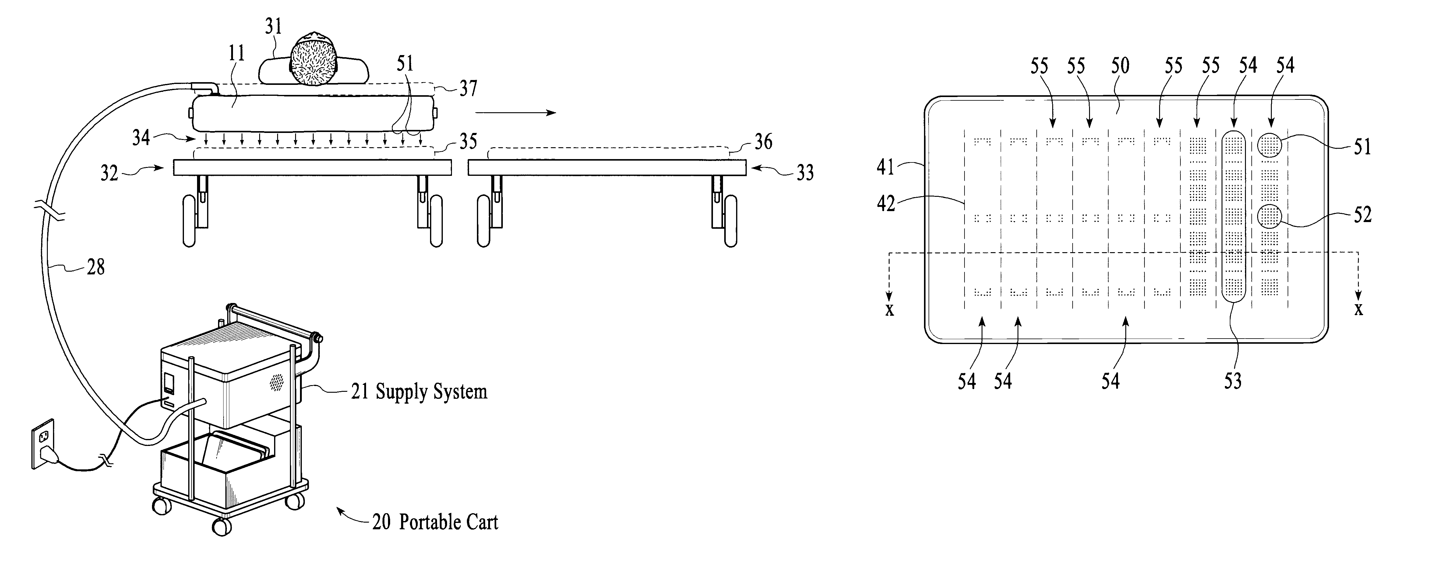
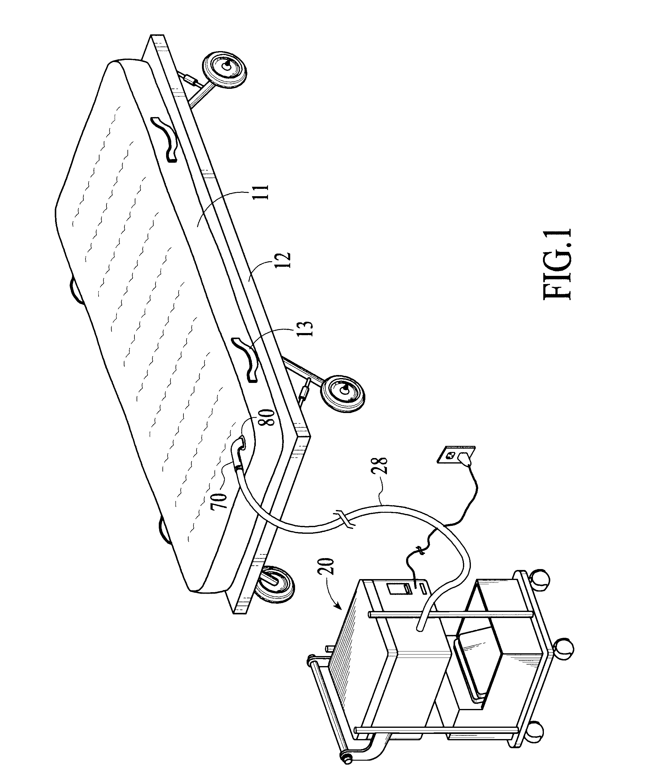
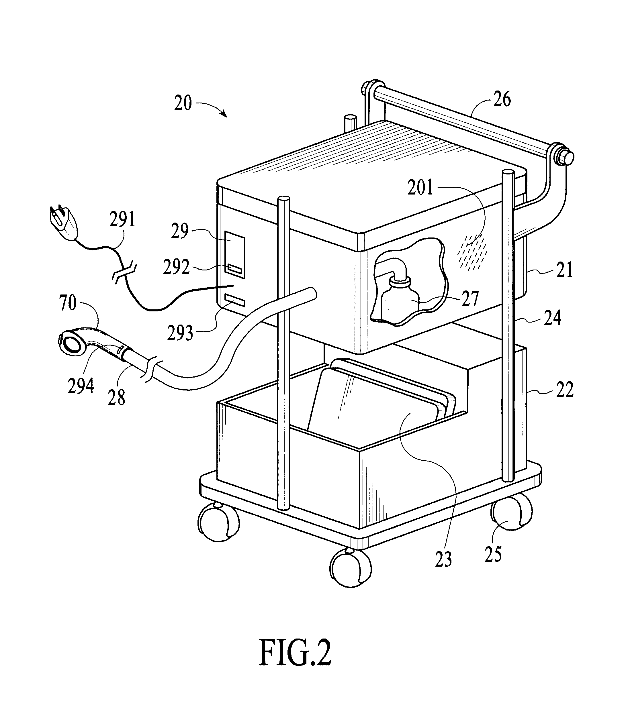
[0022]An embodiment of the present invention is illustrated generally in FIG. 1 as applied to a planar item 12, which in this case is represented as a stretcher. In this embodiment, a portable air supply cart 20 is provided for supplying air to an air mattress 11. The portable air supply cart 20 is connected to the air mattress 11 by means of a flexible hose 28 with a connector 70 which is received by a receptacle 80 integrated into the air mattress 11. The term “air” as used in the present disclosure refers to air or any other gas that can be used to inflate an inflatable mattress. “Air mattress” therefore refers to a mattress that can be inflated with any such gas. The planar item 12 can be any type of bed / surface for supporting a patient, such as a stretcher or hospital bed, and will be referred to herein as a bed apparatus. The inflatable air mattress 11 can be positioned on a firm surface such as planar item 12 illustrated in FIG. 1, or alternatively the air mattress 11 can be ...


PUM


Abstract

A disposable patient transfer mattress includes a rectangular top sheet, a rectangular bottom sheet, internal baffles, and a receptacle configured to receive a connector for supplying air to inflate the mattress. The bottom sheet corresponds to the top sheet, and the periphery of the bottom sheet is joined to the periphery of the top sheet. The internal baffles extend between the top sheet and the bottom sheet. Each baffle is a rectangular sheet with first and second parallel edges, and each baffle is joined to the top sheet along the first edge and to the bottom sheet along the second edge. The bottom sheet has a plurality of holes configured to provide a continuous cushion of air under the mattress when the mattress is inflated. The top sheet, bottom sheet, and internal baffles are made of fabric backed with a thermally weldable material, where the thermally weldable material faces the interior of the mattress for facilitating thermal welding of the baffles to the top surface and the bottom surface.

Description

RELATED APPLICATIONS[0001]This application is a continuation-in-part of U.S. patent application Ser. No. 11 / 538,211 filed Oct. 3, 2006, which in turn is a continuation-in-part of U.S. patent application Ser. No. 11 / 036,413 filed Jan. 14, 2005, which issued as U.S. Pat. No. 7,114,204 on Oct. 3, 2006.FIELD OF THE INVENTION[0002]The present invention relates generally to an apparatus for transferring bed patients, and more particularly to a disposable inflatable mattress for moving a patient on a cushion of air, and to a system including an inflatable mattress connected to an air supply by a quick release connector.BACKGROUND OF THE INVENTION[0003]Non-ambulatory patients who must be supported and moved in a patient facility such as a hospital or a nursing home present substantial challenges when a course of treatment for such patients calls for movement from one location to another. A patient, for example, may need to be moved from a hospital bed, which must remain in the patient's roo...

Claims


Application Information

Patent Timeline
Patent Type & Authority Patents(United States)
IPC IPC(8): A61G7/14A47C27/10
CPCA61G7/1021A61G7/1026A61G2203/90A61G2200/32
Inventor PATRICK, JAMES E.
Owner SAGE PRODS
Why Eureka
Try Eureka