Method of producing a micro-core heat exchanger for a compact indirect evaporative cooler

a technology of indirect evaporative cooler and micro-core heat exchanger, which is applied in the direction of energy-saving heating/cooling, heating types, stationary plate conduit assemblies, etc., can solve the problems of increasing the difficulty of connecting, and affecting the efficiency of cooling

Active Publication Date: 2018-02-22
SEELEY INTERATIONAL
View PDF1 Cites 1 Cited by
  • Summary
  • Abstract
  • Description
  • Claims
  • Application Information

AI Technical Summary

Benefits of technology

[0044]The embossing serves to imprint a design which will ensure not only the desired spacing of the accordion pleated material, but also mechanical durability and structural rigidity of the pleated material. Preferably the embossing forms raised structures such as channel walls or nodes which are oriented not only parallel to the direction of flow as in the heat exchange zone, but also diagonal to the direction of flow, for example in the air inlet and outlet zone, thus imparting rigidity. The embossing preferably further forms lugs and receptacles upon at least some of the plates in order that, when the accordion pleating brings adjacent plate surfaces together, a lug of one plate is captured in a corresponding receptacle of another plate, for example in a snap-fit or friction fit capture upon application of a suitable force. Once captured, the lugs and receptacles serve to secure the accordion pleating in the desired fully folded configuration and to fix the core in working position.

Problems solved by technology

Air is an insulator, so the layer of slow moving air directly adjacent the plates constitutes an obstruction to heat transfer.
However, as turbulence increases, so does resistance to flow.
However, as the sheet spacing becomes thinner, a problem arises in manufacturing.
It becomes increasingly problematic to connect, in a commercial scale manufacturing process, the inlet and outlet manifolds to the smaller and smaller wet and dry flow passages.
This is time and labour intensive.

Method used


Image

  • Method of producing a micro-core heat exchanger for a compact indirect evaporative cooler
  • Method of producing a micro-core heat exchanger for a compact indirect evaporative cooler
  • Method of producing a micro-core heat exchanger for a compact indirect evaporative cooler

Examples


Embodiment Construction

[0069]Flocking is the process of depositing many small fiber particles (called flock) onto a surface. Flocking is defined as the application of fine particles to adhesive coated surfaces. In a flocking machine the “flock” is given a high-voltage negative charge while the horizontal substrate is grounded. Flock material flies vertically onto the substrate attaching to previously applied glue.

[0070]Pleating of materials in industrial scale manufacturing processes is well known, and examples of pleated materials include air filters and oil filters.

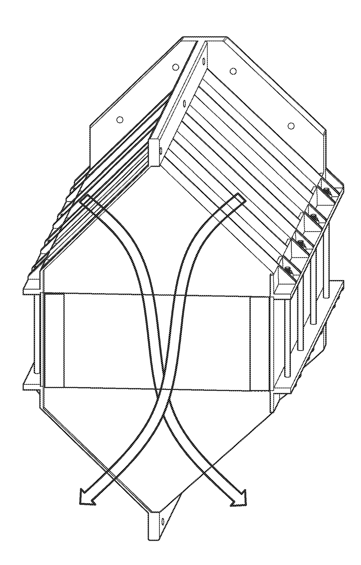
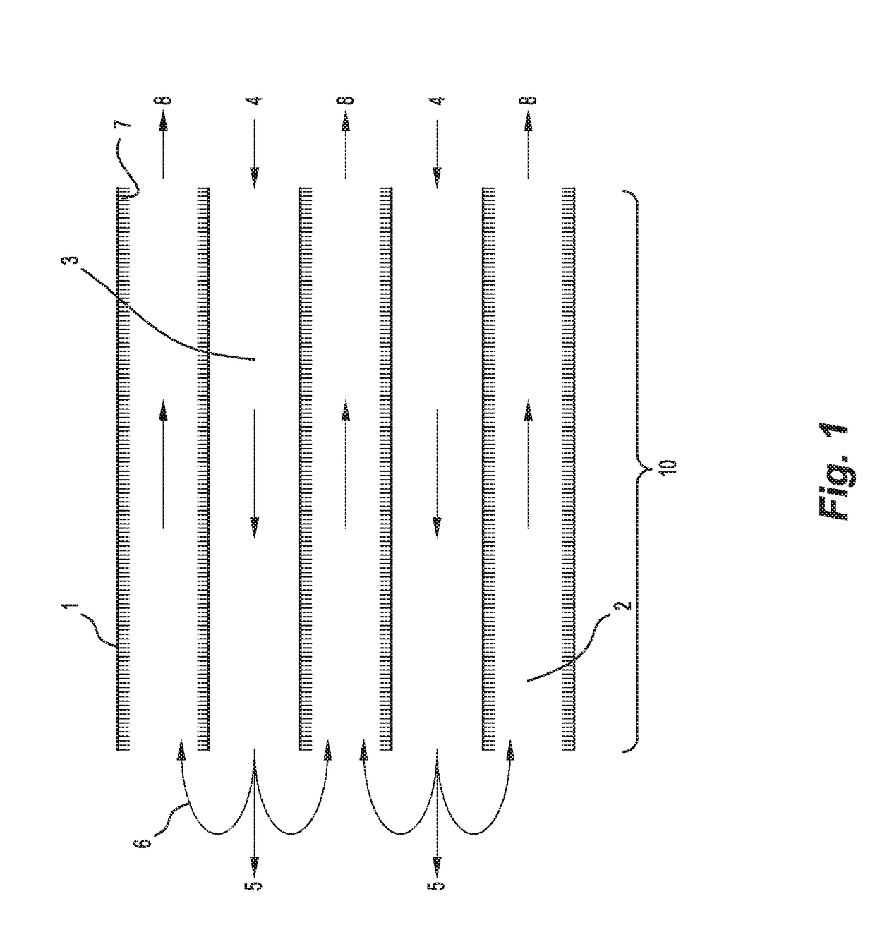
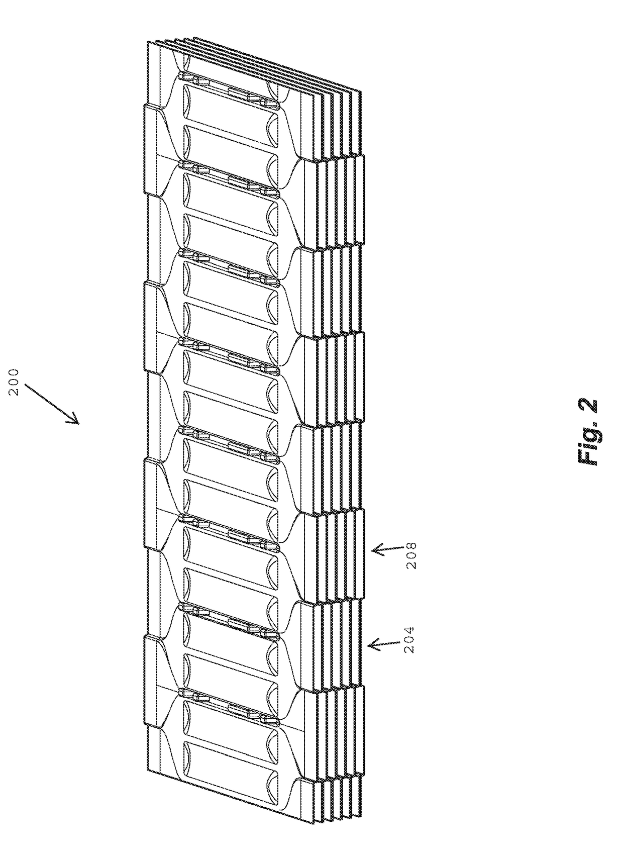
[0071]Embossing is also well known. EP 0 055 711 B1 entitled “Low Profile Heat Exchanger and Method of Making the Same” teaches forming a heat exchange core for a heater comprising pleating a unitary, elongated strip of heat conducting material to form a plurality of walls defining a fluid passages therebetween. However, air flows parallel to the folds, not transverse to the folds. U.S. Pat. No. 6,892,795 entitled “Embossed Regenerator Matrix...


PUM

PropertyMeasurementUnit
hydrophobicaaaaaaaaaa
surface areaaaaaaaaaaa
mechanical durabilityaaaaaaaaaa

Abstract

An indirect evaporative cooler core is manufactured from a continuous sheet of hydrophobic material. Flocking is provided on at least a partial surface area of at least one side of the sheet, to render the flocked surface area wettable. Air flow guiding structures are formed upon at least one of the first side and the second side of the sheet. Fold lines are defined in the sheet defining plates extending between adjacent fold lines. Slits are formed along the fold lines. Accordion pleating the sheet at the fold lines forms alternating wet and dry passages between the plates, the wet passages formed between opposing wettable surfaces, the dry passages formed between non-flocked surfaces, and the accordion pleating causes the slits in the folds to open and form air inlets and outlets in communication with the air flow passages.

Description

CROSS-REFERENCE TO RELATED APPLICATIONS[0001]This application claims the benefit of U.S. Provisional Patent Application No. 62 / 119,718 filed 23 Feb. 2015, which is incorporated herein by reference.TECHNICAL FIELD[0002]The invention relates to an indirect evaporative cooler, and in particular, an indirect evaporative cooler with a compact core as disclosed for example in International Patent Application No. PCT / AU2015 / 050528 filed 8 Sep. 2015 (formerly U.S. Provisional Application No. 62 / 047,160 filed Sep. 8, 2014), entitled “COMPACT INDIRECT EVAPORATIVE COOLER”, and assigned to the present assignee, the disclosure of each of which is incorporated herein by reference. The compact core can also be used in a heat recovery heat exchanger.BACKGROUND OF THE INVENTION[0003]At its core, a modern evaporative cooler typically comprises a stack of thin parallel spaced-apart plates. The plates define alternating wet and dry air-flow passages. In the wet passages a “working” airstream passes ove...

Claims


Application Information

Patent Timeline
Patent Type & Authority Applications(United States)
IPC IPC(8): F24F1/00F28F21/06F28F13/18F24F1/0067
CPCF24F1/0059F28F21/066F28F13/187F24F2001/0092F28F2245/02F28F2245/04F28D9/0025F24F1/0007F24F1/0067F24F5/0035Y02B30/54
Inventor SWINDON, DAVID MARKCHEN, NANMAHONEY, SHAUNGILBERT, ROBERT WILLIAM
Owner SEELEY INTERATIONAL
Why Eureka
Try Eureka