Method and apparatus for automatic support generation for an object made by means of a rapid prototype production method

a production method and automatic support technology, applied in the direction of computer control, process and machine control, instruments, etc., can solve the problems of support being considered as lost material, curling effect, and tendency to deform stereo lithography resin, so as to facilitate separation of support and object, reduce material cost and production time, and minimize the effect of supporting material cos

Active Publication Date: 2010-09-09
MATERIALISE NV
View PDF23 Cites 77 Cited by
  • Summary
  • Abstract
  • Description
  • Claims
  • Application Information

AI Technical Summary

Benefits of technology

[0013]Another advantage of some embodiments of the present invention is to lower the material cost and production time of the support.
[0019]generating support data by transforming the support mesh into a support structure.
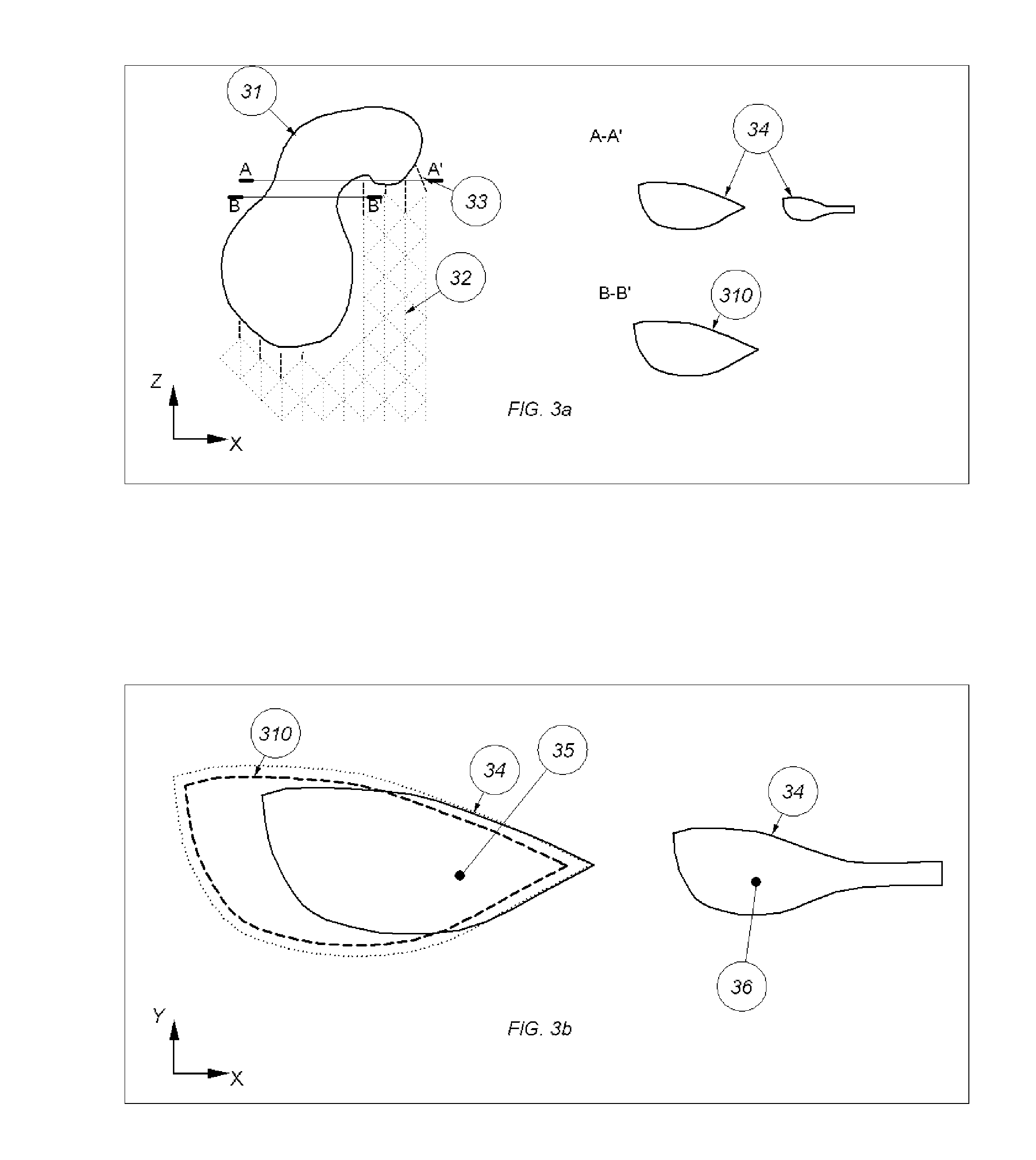
[0020]In preferred embodiments, the support region of a layer of the object may be obtained by Boolean subtracting the underlying layer of said layer from said layer. Said underlying layer may be outward offset to account for the self-supporting capacity of said layer. The support region obtained this way may be further divided into a coarse and detailed support region. In case of a coarse support region, support points may be uniformly distributed on a inward offset boundary, such that the distance between neighboring points never exceeds a predefined distance. This distance may be defined as twice the critical overhang. The region obtained by Boolean subtracting circles (or regular polygons) centered around each of the support points on said boundary with a radius preferably set to be equal to the critical overhang from said coarse region, is then divided into a coarse and a detailed region. The support points in these regions are then further recursively defined. In case of a detailed support region, support points may be uniformly distributed on the skeleton of said detailed support region.
[0021]In preferred embodiments, at least a portion of the initial mesh may be regular. More preferably, the 3-D mesh may consist of vertical walls based on a rhombus pattern, including the vertical diagonal of the rhombus, whereby parallel walls are placed at half the width of the rhombus and orthogonal walls intersect at the horizontal diagonal of any rhombus.
[0022]In certain embodiments, prior to Boolean subtracting the 3-D object from the initial mesh, the boundary of the 3-D object may be offset outward to facilitate separating the support from the object.
[0023]It is another aspect of the present invention to provide a method to minimize the support material cost.

Problems solved by technology

For example, stereo lithography resins have a tendency to deform during the building process because of internal stresses generated by shrinkage resulting in curling effects.
Moreover as the support is removed once the object is built, the support is considered as lost material.
However, as this tends to be a tedious and labor intensive task, software has been developed in the past to automatically design the support structures and transcribe them in STL or any other surface format which gives a description of the special structure.
One of the disadvantages of the above-mentioned software tools is that often, the designed support does not sufficiently support at least one region of the object.
As mentioned earlier, this is a tedious and labor intensive task.

Method used


Image

  • Method and apparatus for automatic support generation for an object made by means of a rapid prototype production method
  • Method and apparatus for automatic support generation for an object made by means of a rapid prototype production method
  • Method and apparatus for automatic support generation for an object made by means of a rapid prototype production method

Examples


Embodiment Construction

[0060]In the following detailed description of the preferred embodiments, reference is made to the accompanying drawings, which form a part hereof, and within which are shown by way of illustration specific embodiments by which the invention may be practiced. The drawings described are only schematic and are non-limiting. In the drawings, the size of some of the elements may be exaggerated and not drawn on scale for illustrative purposes. It is to be understood that other embodiments may be utilized and structural changes may be made without departing from the scope of the invention.

[0061]Furthermore, the terms first, second, third and the like in the description and in the claims, are used for distinguishing between similar elements and not necessarily for describing a sequential or chronological order. It is to be understood that the terms so used are interchangeable under appropriate circumstances and that the embodiments of the invention described herein are capable of operation...


PUM

PropertyMeasurementUnit
distanceaaaaaaaaaa
radiusaaaaaaaaaa
widthaaaaaaaaaa

Abstract

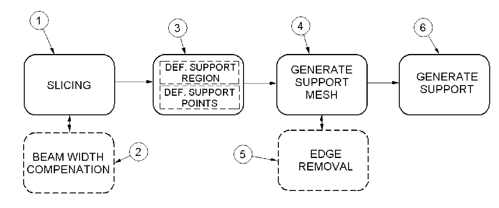
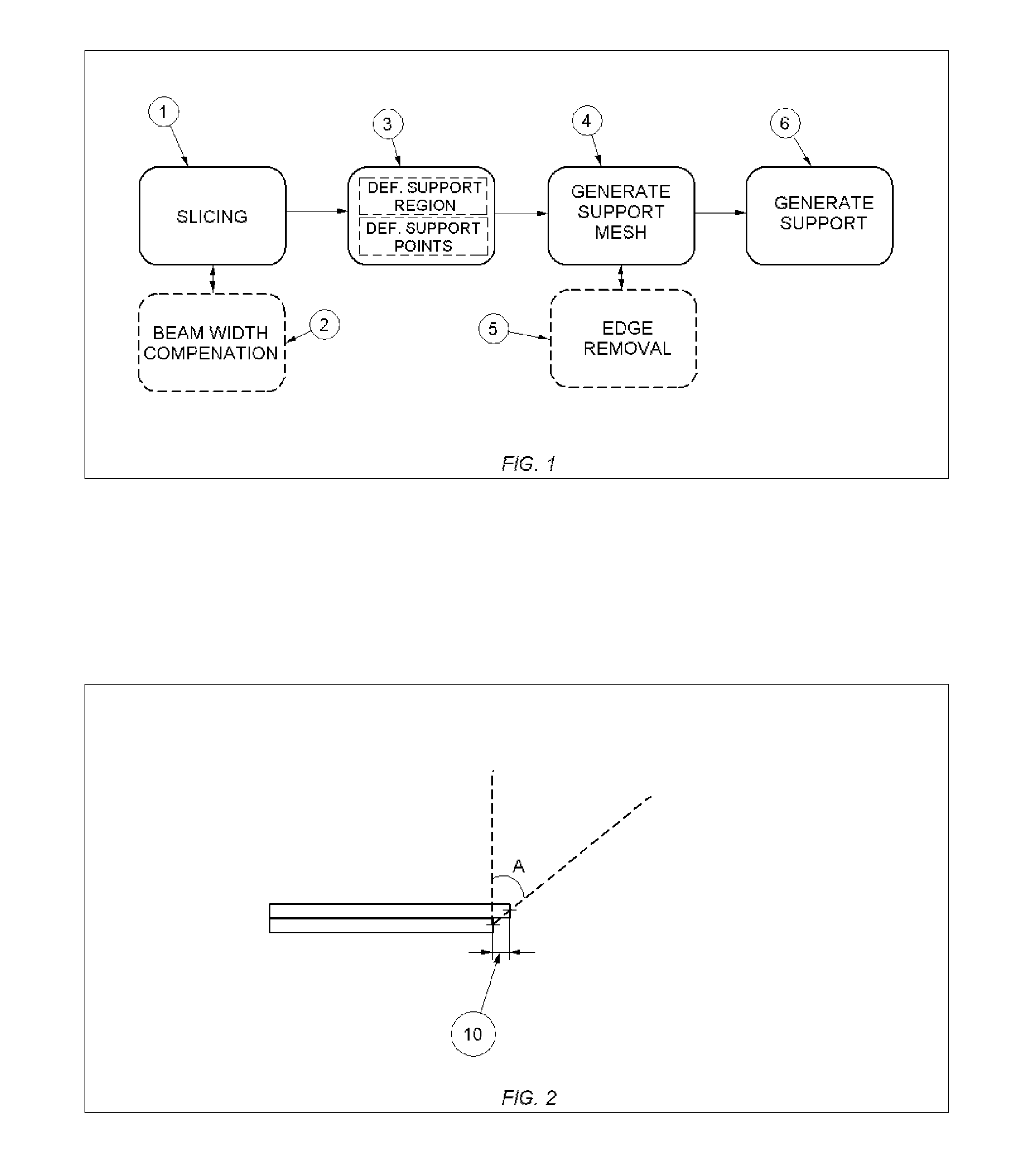
The present invention is directed to an improved method for supporting an object made by means of stereo lithography or any other rapid prototype production method. The generation of the support begins by determining the region that requires support in each layer of the object and defines a number of support points in this region. In a next step, a support mesh is generated connected to the object using these support points. The present invention also discloses different techniques that reduce superfluous edges to further optimize the support mesh. Finally, a support is generated from this support mesh. The present invention may facilitate the generation of supports data by employing more automation and less user analysis.

Description

FIELD OF THE INVENTION[0001]The present invention relates to methods for creating an object made by means of stereo lithography or another rapid prototype production method and, more particularly, is directed to an improved method for generating a support for an object made by means of stereo lithography or another rapid prototype production method. The present invention also relates to the support created by any of the above methods and to software adapted to carry out any of the above methods. The present invention also relates to a controller for controlling a rapid prototype production machine.BACKGROUND OF THE INVENTION[0002]Rapid Prototyping and Manufacturing (RP&M) can be defined as a group of techniques used to quickly fabricate a scale model of an object typically using three-dimensional (3-D) computer aided design (CAD) data of the object. Currently, a multitude of Rapid Prototyping techniques is available, including stereo lithography (SLA), Selective Laser Sintering (SLS...

Claims


Application Information

Patent Timeline
Patent Type & Authority Applications(United States)
IPC IPC(8): G06F17/50
CPCG06T17/10B29C67/0092G06T19/00B29C64/386B29C64/40B33Y50/00B33Y80/00B33Y50/02G05B15/02
Inventor EGGERS, GERALDRENAP, KURT
Owner MATERIALISE NV
Why Eureka
Try Eureka