Battery Pack

a battery pack and structure technology, applied in the direction of battery/fuel cell control arrangement, cell components, propulsion by batteries/cells, etc., can solve the problems of reducing work efficiency, reducing the work efficiency of assembling the battery pack and fixing it to the vehicle, etc., to achieve the effect of reducing material cost and improving efficiency in the assembly work of the battery pack

Inactive Publication Date: 2008-12-25
TOYOTA JIDOSHA KK
View PDF4 Cites 78 Cited by
  • Summary
  • Abstract
  • Description
  • Claims
  • Application Information

AI Technical Summary

Benefits of technology

[0010]The problem to be solved by the present invention lies in that, in assembling a battery pack and in fixing the battery pack to a vehicle, great many bolt assembly steps are required and consequently the work efficiency is lowered. Accordingly, the present invention is made to provide a battery pack that can improve the efficiency in fastening works by greatly reducing steps of assembling with bolts and the like in assembling a battery pack and in fixing the battery pack to a vehicle.
[0012]With the battery pack according to the present invention, the interposed member arranged between the upper case flange portion and the lower case flange portion is fixed based upon the fastening and fixing of the upper case flange portion and the lower case flange portion by the fastening member, and the battery assembly is positioned and fixed inside the battery case. This makes it possible to concurrently achieve positioning and fixing of the battery assembly within the battery case and fastening and fixing of the upper case to the lower case. Further, it also becomes possible to perform the fastening work with the fastening member from the upper case side. As a result, the efficiency in the assembly work of the battery pack can be improved. Still further, since reduction in the number of fastening members can be realized, reduction in the material cost can be achieved.

Problems solved by technology

Thus, great many bolt assembling steps have been required in assembling battery pack 1E and fixing the same to the vehicle, which has been the factor of reducing the work efficiency.
It employs a fixing structure where mounting of the upper case to the lower case and mounting of the battery pack itself to the vehicle are respectively attained with different bolts, and therefore the work efficiency in assembling the battery pack and in fixing it to the vehicle is not fully improved.

Method used


Image

  • Battery Pack
  • Battery Pack
  • Battery Pack

Examples


first embodiment

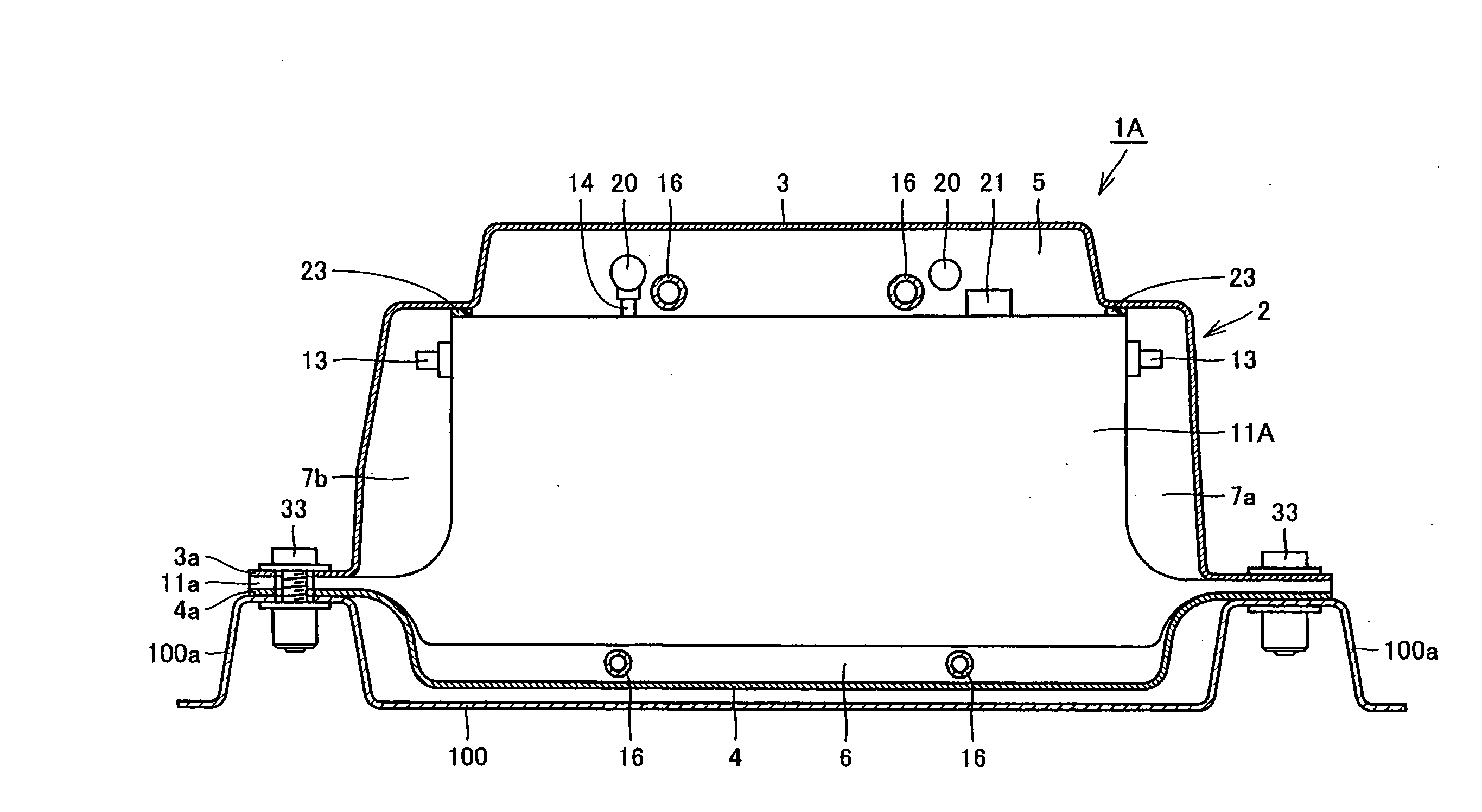
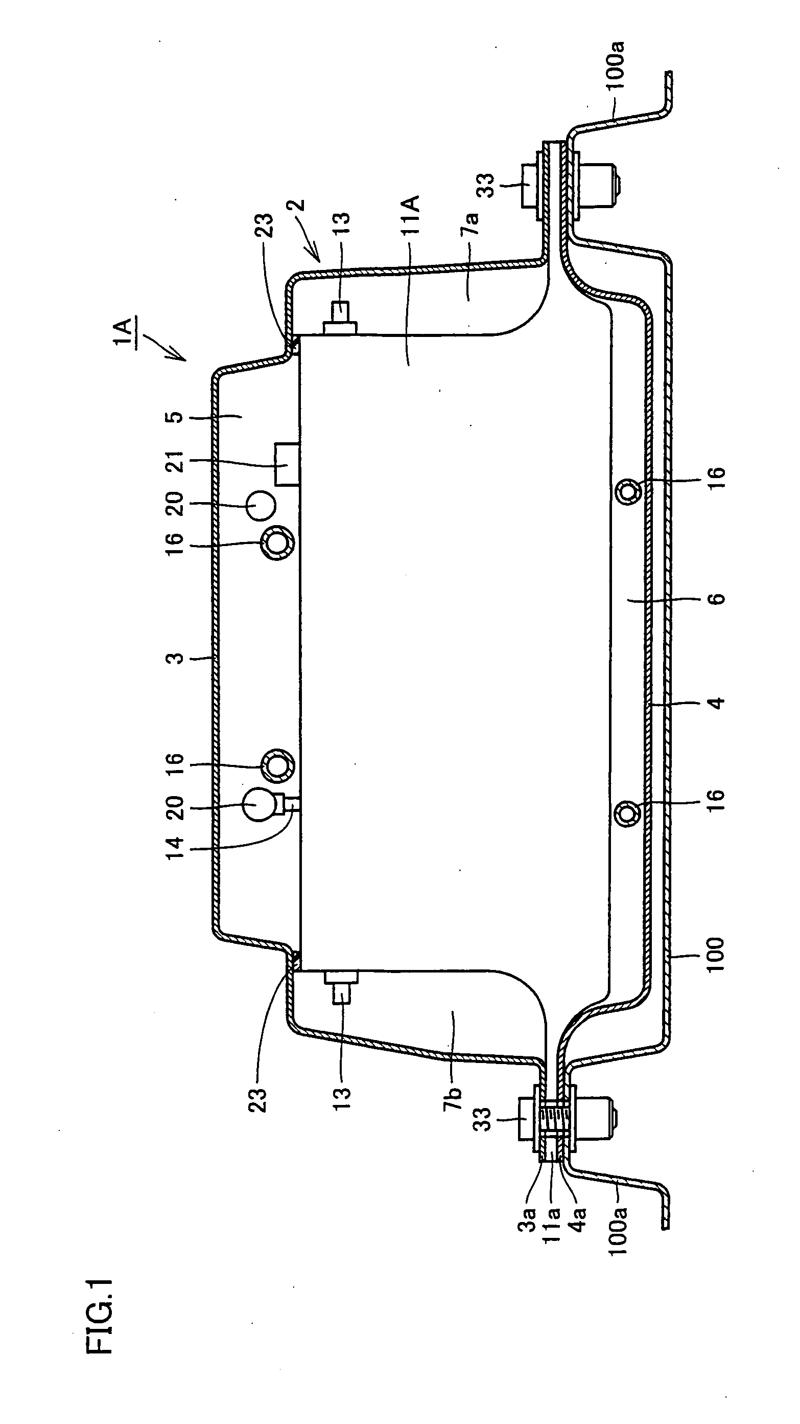
[0024]First, referring to FIGS. 1 and 2, a battery pack of the present embodiment will be described. FIG. 1 is a schematic cross sectional view of battery pack 1A in a direction perpendicular to a stacking direction of battery modules 11A. FIG. 2 is an overall perspective view showing a structure of a battery assembly 10A of the first embodiment of the present invention. While battery module 11A of the present embodiment is shown as of nickel-cadmium battery type, other batteries such as nickel-hydrogen battery and the like can be employed.

[0025]Battery pack 1A of the present embodiment is a battery pack storing, inside a battery case 2, a battery assembly 10A in which a plurality of battery modules 11A are stacked. Battery case 2 has an upper case 3 and a lower case 4. Upper case 3 is provided with an upper case flange portion 3a that projects laterally and that extends in the stacking direction (the direction perpendicular to the surface of FIG. 1) of battery modules 11A. Similarl...

second embodiment

[0031]Next, referring to FIGS. 3 and 4, a battery pack and a fixing structure of the battery pack of the present embodiment will be described. FIG. 3 is a schematic cross sectional view of battery pack 1B in the direction perpendicular to the stacking direction of battery modules 11B. FIG. 4 is an overall perspective view showing a structure of battery assembly 10B of the present embodiment. Battery modules 11B of the present embodiment are of nickel-cadmium battery type.

[0032]Comparing battery pack 1B of the present embodiment with battery pack 1A of the first embodiment, a difference lies in the fixing structure of battery modules 11B to battery case 2. Specifically, as to battery pack 1B of the present embodiment, similarly to the first embodiment, upper case 3 and lower case 4 are provided with upper case flange portion 3a and lower case flange portion 4a extending in the stacking direction of battery modules 11B. Battery assembly 10B is provided with battery module projecting p...

third embodiment

[0038]Next, referring to FIGS. 5 and 6, a battery pack 1C of the present embodiment will be described. FIG. 5 is an overall perspective view showing a structure of battery pack 1C and battery assembly 50A of the present embodiment. FIG. 6 is a partial exploded perspective view showing a detailed structure of battery assembly 50A. Battery modules 54A (described later) of the present embodiment is of lithium-ion battery type.

[0039]Battery pack 1C of the present embodiment is a battery pack in which battery assembly 50A is stored inside battery case 2. Similarly to the above-described embodiments, battery case 2 has upper case 3 and lower case 4. Upper case 3 is provided with upper case flange portion 3a that laterally projects and that extends in the stacking direction of battery modules 54A (described later) constituting battery assembly 50A. Similarly, lower case 4 is provided with lower case flange portion 4a that laterally projects and that extends in the stacking direction of bat...


PUM

PropertyMeasurementUnit
areaaaaaaaaaaa
heightaaaaaaaaaa
structureaaaaaaaaaa

Abstract

In a battery pack, battery pack flange portions are provided at opposing sides of a battery assembly along a stacking direction of battery modules, so as to project laterally. The battery module flange portions are interposed between an upper case flange portion and a lower case flange portion when the upper case flange portion and the lower case flange portion are overlaid, and fastened and fixed concurrently by bolts. The bolts are also used in fixing the battery pack to a vehicle. With this configuration, a battery pack that can reduce assembly steps with the bolts and the like to improve efficiency in the fastening work can be provided.

Description

TECHNICAL FIELD[0001]The present invention relates to a structure of a battery pack incorporated into a vehicle such as an electric vehicle.BACKGROUND ART[0002]In recent years, electric vehicles that employ a motor as a driving source, or what is called hybrid vehicles wherein a motor as a driving source and other driving source are combined, are put into practical use. Such a vehicle incorporates a battery for supplying electricity as energy to the motor. As such a battery, for example a secondary battery represented by a nickel-cadmium battery, a nickel-hydrogen battery, a lithium ion battery and the like that can repeatedly be charged and discharged are used.[0003]A secondary battery is constituted of battery modules in which battery cells are stacked. The battery modules are stored inside a battery case, and in this state, incorporated into a vehicle. This battery case and the battery modules together with other internal components stored inside the battery case are referred to ...

Claims


Application Information

Patent Timeline
Patent Type & Authority Applications(United States)
IPC IPC(8): H01M2/02B60L11/18H01M50/211H01M50/249H01M50/262H01M50/271H01M50/528
CPCH01M2/1016Y02E60/122H01M2/1077H01M2/1083H01M2/22H01M10/0525Y02T10/7005Y02T10/705H01M10/625H01M10/6563H01M10/647H01M10/6557H01M10/613B60L58/26B60L50/64H01M2/1072Y02E60/10Y02T10/70H01M50/528H01M50/249H01M50/211H01M50/262H01M50/271
Inventor WATANABE, KOOYANAGI, HAJIME
Owner TOYOTA JIDOSHA KK
Why Eureka
Try Eureka