Process of initiating a calendar

Inactive Publication Date: 2000-12-12
VALMET TECHNOLOGIES INC
View PDF16 Cites 6 Cited by
  • Summary
  • Abstract
  • Description
  • Claims
  • Application Information

AI Technical Summary

Benefits of technology

The object of the invention is to provide a process and apparatus which eliminates or at least minimizes the disadvantages mentioned above. This is achieved according to one aspect of the invention;
By a method for operating a calender, comprising a cylindrical heated roll and a flexible belt surrounding a stationary support beam, which supports at least one actuator which may urge a concave load shoe against the heated roll by means of said flexible belt to form an extended and heated nip through which a fiber web passes to be calendered, and a separating mechanism for having at least one of the rolls movable into and away from the nip characterised in that said flexible belt is a flexible tubular jacket which forms a part of an enclosed shoe roll such that the ends of said jacket have end walls mounted thereto, which end walls are rotatably mounted in relation to said support beam, and in that at least one of said end walls is driven by means of a drive arrangement, which drive arrangement may be activated to drive the end walls and thereby also the jacket independently of its position in relation to the fiber web or the heated roll.
The advantages of the present invention are several. The drive arrangement according to the invention enables opening and closing of

Problems solved by technology

A disadvantage by using the above mentioned method is that the high pressure acting on the web may cause excessive compaction of the web.
As a result the thickness of the paper will be significantly reduced leading to relatively poor stiffness of the web after the calendering.
A relatively recent problem in relation to heat calendering is the achievement of sufficient heat transfer, due to the trend towards higher and higher speed of the web.
The endless flexible belt used in an extended nip is preferably made of a material that comprises polymers, resulting in relatively poor heat resistance, i.e. if the heat exceeds a certain temperature, normally about 80-100.degree. C., the flexible belt will be destroyed.
However, if the paper web is broken, th

Method used


Image

  • Process of initiating a calendar
  • Process of initiating a calendar
  • Process of initiating a calendar

Examples


Embodiment Construction

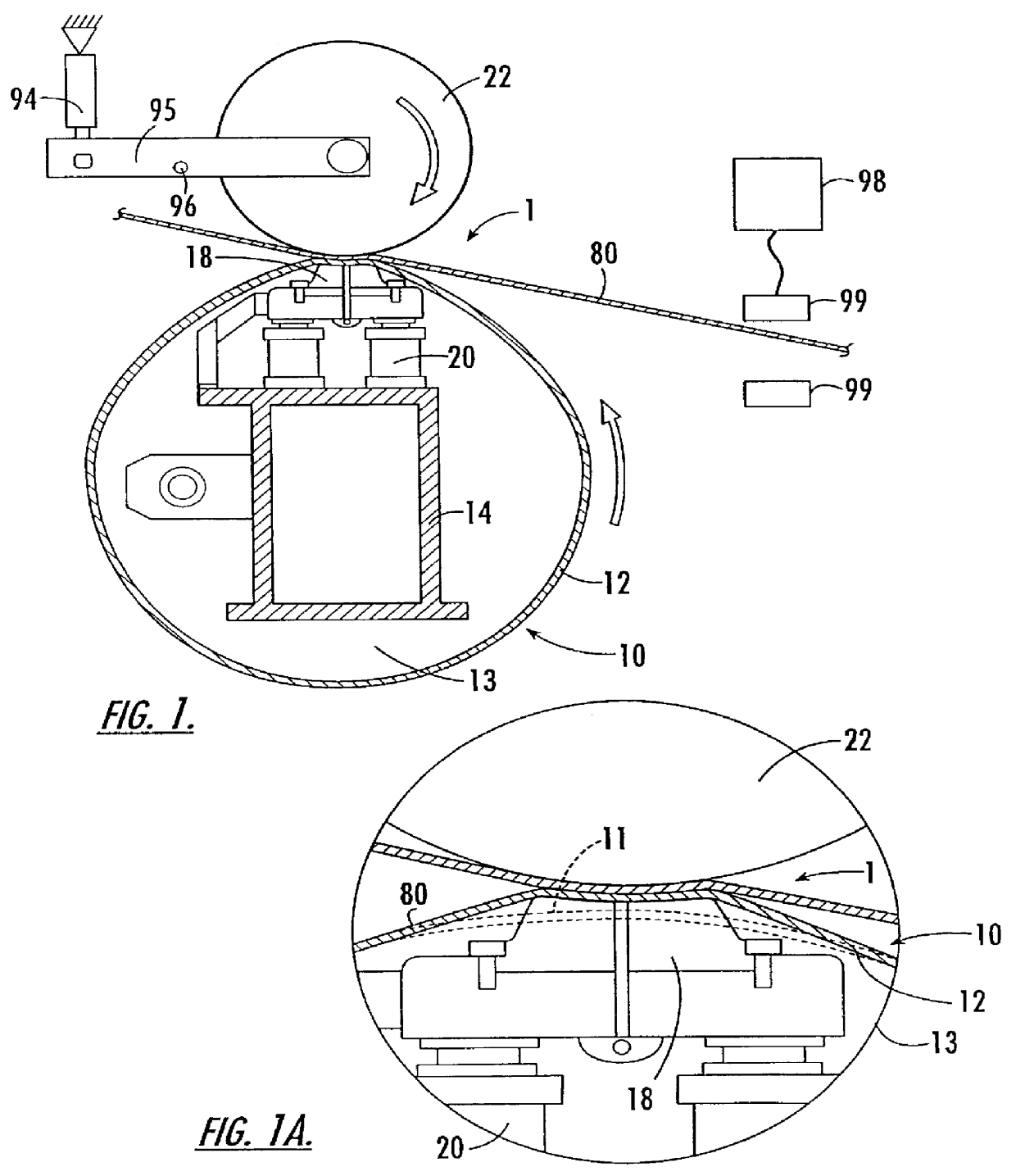
In FIG. 1 there is shown a fiber web 80 passing through an extended and heated nip 1. The nip 1 is formed by an enclosed shoe roll 10 positioned on the lower side in relation to the fiber web 80. On the upper side of the fiber web 80 there is shown a heated roll 22. The enclosed shoe roll 10 comprises a liquid impermeable flexible jacket 12, e.g. of a conventional type consisting of reinforced polyurethane. A stationary non-rotatable support beam 14 supports at least one load shoe 18. Between the load shoe 18 and the support beam 14 there is an actuator 20, in the preferred embodiment hydraulic pistons. for urging the concave load shoe 18 and thereby also the flexible jacket against the counter-roll 22. It should be noted that (contrary to what is "normal practice") the jacket is urged out of its unloaded position in a direction away from the center of the enclosed shoe roll. (In known shoe type presses the counter roll depresses the jacket inwardly.)T he jacket 12 is attached to th...


PUM


Abstract

The invention relates to a method for operating a calender, comprising a cylindrical heated roll and a flexible belt surrounding a stationary support beam which supports at least one actuator which may urge a concave load shoe against the heated roll by means of said flexible belt to form an extended and heated nip through which a fiber web passes to be calendered and a separating mechanism for having at least one of the rolls movable into and away from the nip characterised in that said flexible belt is a flexible tubular jacket which forms a part of an enclosed shoe roll such that the ends of said jacket have end walls mounted thereto, which end walls are rotatably mounted in relation to said support beam, and in that at least one of said end walls is driven by means of a drive arrangement which drive arrangement may be activated to drive the end walls and thereby also the jacket independently of its position in relation to the fiber web or the heated roll.

Description

This invention relates to a method and apparatus for performing calendering of a fiber web, preferably using an enclosed shoe roll.PRIOR ART AND PROBLEMSCalendering of paper is performed in order to achieve a smooth surface of a fiber web, e.g. paper. Traditionally this is achieved by using two counter-acting rolls forming a nip within which a high pressure is applied to the paper surface in order to even out irregularities of the paper surface so as to form a smooth surface. A disadvantage by using the above mentioned method is that the high pressure acting on the web may cause excessive compaction of the web. As a result the thickness of the paper will be significantly reduced leading to relatively poor stiffness of the web after the calendering.The above mentioned disadvantage can be reduced by using heat in combination with a relatively moderate pressure. The reason for this is that the fibers of the paper are plasticized if the temperature is sufficiently high (The temperature ...

Claims


Application Information

Patent Timeline
IPC IPC(8): D21G1/02D21F3/02D21G1/00
CPCD21G1/0006D21G1/0013D21G1/002D21G1/0226D21G1/02D21G1/0213D21G1/006
Inventor SAFMAN, NILS-ERIKBERGLIND, THOMAS
Owner VALMET TECHNOLOGIES INC
Why Eureka
Try Eureka