Microplate carrier having magnets

a microplate carrier and magnet technology, applied in the field of microplate carriers, can solve the problems of inefficient washing, inadequate liquid exchange, and the floor of the well, and achieve the effect of minimizing or eliminating the disadvantages

Active Publication Date: 2009-03-12
TECAN TRADING AG
View PDF26 Cites 16 Cited by
  • Summary
  • Abstract
  • Description
  • Claims
  • Application Information

AI Technical Summary

Benefits of technology

[0008]The object of the present invention is to suggest an alternative device which eliminates or at least minimizes the disadvantages known from the prior art.

Problems solved by technology

These annular magnets have the disadvantage, however (cf., for example, EP 0 589 636 B1), that only a specific type of microplates (e.g., having V floor or round floor) may be used in an optimized way.
However, such devices have the disadvantage that the entire floor of the well, or at least the lowest point (and thus the preferred suction location) in this well is occupied by concentrated magnetic particles.
A relatively large residual volume of liquid thus results in the well, which may not be suctioned off without significant loss of magnetic particles.
In addition, this residual volume results in inadequate liquid exchange and thus inefficient washing.
These two carriers for microplates known from the prior art have the disadvantage that the concentration of the magnetic particles occurs at different points in the wells of a microplate, because of which the automation of a washing process is made more difficult, for example.
If microplates having flat floor wells are used, central suctioning results in an annular residual volume which impairs the washing efficiency, however.

Method used


Image

  • Microplate carrier having magnets
  • Microplate carrier having magnets

Examples


Embodiment Construction

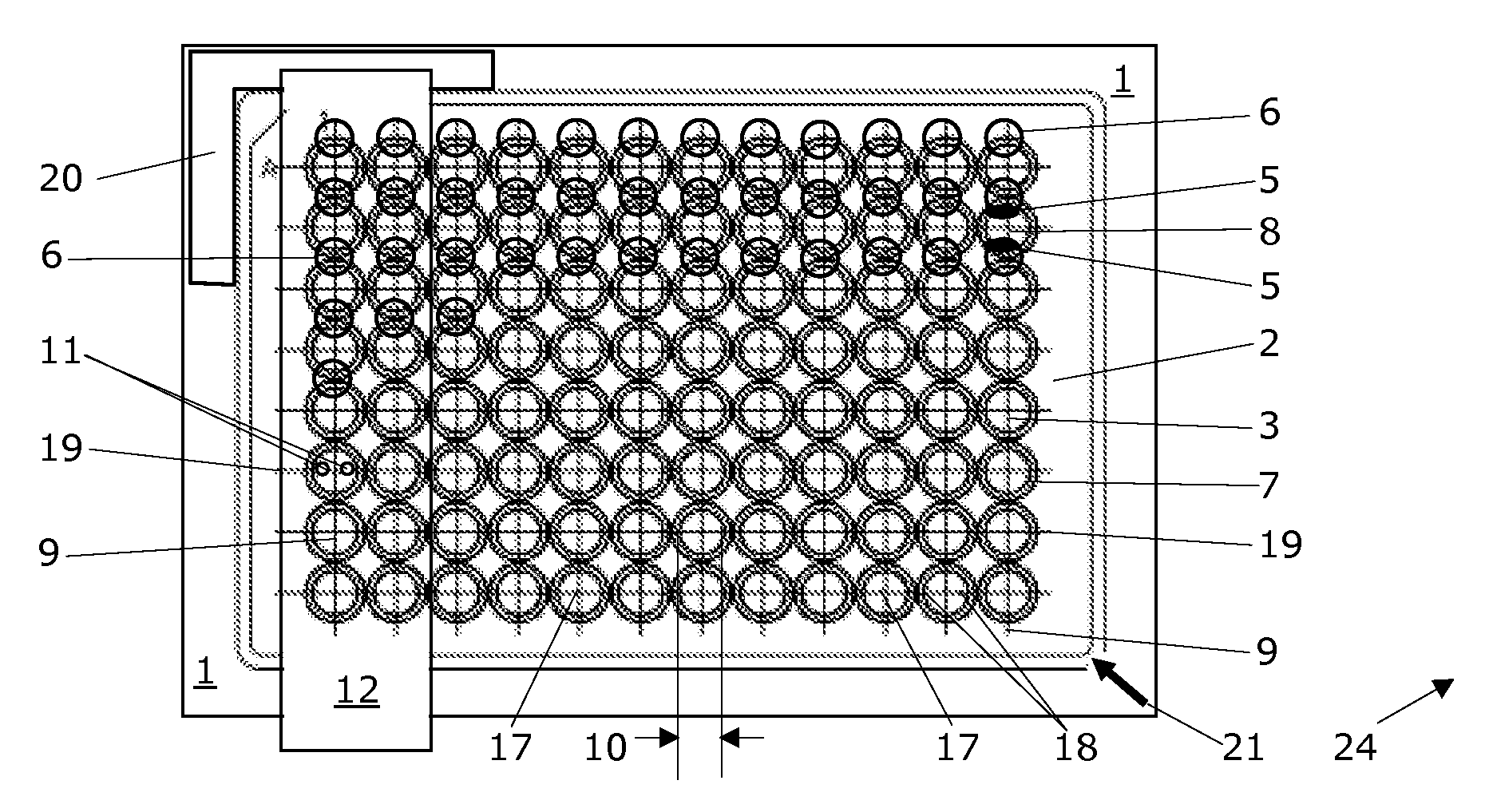
[0023]The FIG. 1 shows a top view of a microplate carrier 1 according to a first embodiment having 108 permanent magnets 6. The microplate carrier 1 is capable of receiving a microplate 2. In connection with the present invention, all multi-well plates having a plurality of wells or containers which is situated in an array are referred to as microplates. Especially preferred microplates have at least approximately the mass and the footprint of a microplate according to the SBS standard, as published by the American National Standards Institute (ANSI).

[0024]For example, microplates whose wells are equipped with a round floor, flat floor, or V floor are known. V floor wells having circular or square cross sections are known, so that the floor area is implemented as more conical or as pyramidal. The wells may be implemented as “normal wells” or also as “deep wells”. Wells in the shape of truncated cones or truncated pyramids are also known per se. All microplates having greatly varying...


PUM

PropertyMeasurementUnit
heightaaaaaaaaaa
diameteraaaaaaaaaa
magnetic fieldsaaaaaaaaaa

Abstract

Relates to a microplate carrier (1) for a microplate (2), in whose wells (3) magnetic particles (5), which are suspended in a liquid (4), with or without samples adhering thereto are located, the microplate carrier (1) comprising permanent magnets (6) generating magnetic fields which are implemented to collect and retain the magnetic particles (5) on the floor (14) and/or on the walls (7) of the wells (3) of this microplate (2). The microplate carrier (1) according to the invention is characterized in that it comprises two permanent magnets (6) situated diametrically opposite in relation to the well (3) for each well (3) of the microplate (2), which have the same polarity directed toward the well (3) and whose magnetic axis (25) is at least essentially perpendicular to the footprint of the microplate (2) to be placed. A corresponding method based on the use of the microplate carrier (1) is also disclosed.

Description

RELATED PATENT APPLICATIONS [0001]This patent application claims priority of the U.S. provisional application No. 60 / 969,236 as well as from the Swiss patent application No. 01360 / 07, both filed on Aug. 31, 2007. The entire content of these two priority defining applications is incorporated herein by explicit reference for any purpose.RELATED FIELD OF TECHNOLOGY [0002]The invention relates to a microplate carrier for microplates, in whose wells magnetic particles, which are suspended in a liquid, with or without samples adhering thereto are located. The microplate carrier comprises permanent magnets which generate magnetic fields, which are implemented to collect and retain the magnetic particles on the floor and / or on the walls of the wells of this microplate. Cannulas of a microplate washing device for suctioning at least a part of the liquid may thus be lowered into the wells, for example, without these cannulas contacting the concentrated magnetic particles. The invention additi...

Claims


Application Information

Patent Timeline
Patent Type & Authority Applications(United States)
IPC IPC(8): G01N1/34B01L9/00G01N1/28
CPCB01L3/5085B01L9/523G01N35/0098B03C1/288B03C2201/18B01L2300/0829B03C1/0332
Inventor FASCHING, GERHARDHRUSCHKA, TERESANIGGL, LUTZNIKLAUS, PATRICK
Owner TECAN TRADING AG
Why Eureka
Try Eureka