Resonating injection molding machine and process for its operation

Inactive Publication Date: 2001-03-20
ATECS MANNESMANN GMBH +1
View PDF7 Cites 36 Cited by
  • Summary
  • Abstract
  • Description
  • Claims
  • Application Information

AI Technical Summary

Problems solved by technology

This type of apparatus for mixing the plastic melt requires relatively high mechanical driving power and causes wear to both the screw and the cylinder.
This requirement substantially lengthens the structural form of the injection unit in question.
In addition, no influence can be exerted on the coefficient of friction of the melt as it passes throu

Method used


Image

  • Resonating injection molding machine and process for its operation
  • Resonating injection molding machine and process for its operation
  • Resonating injection molding machine and process for its operation

Examples


Embodiment Construction

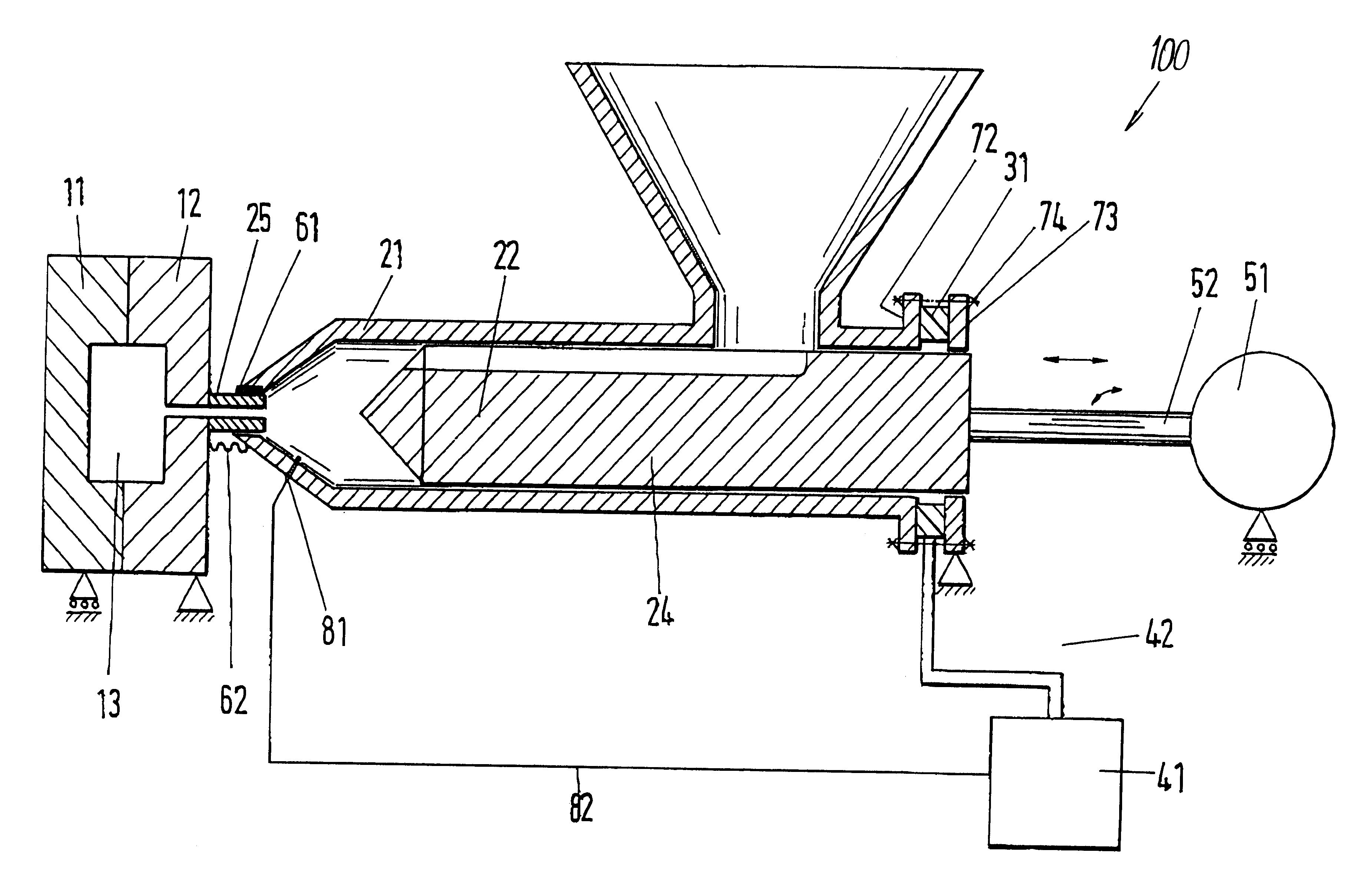
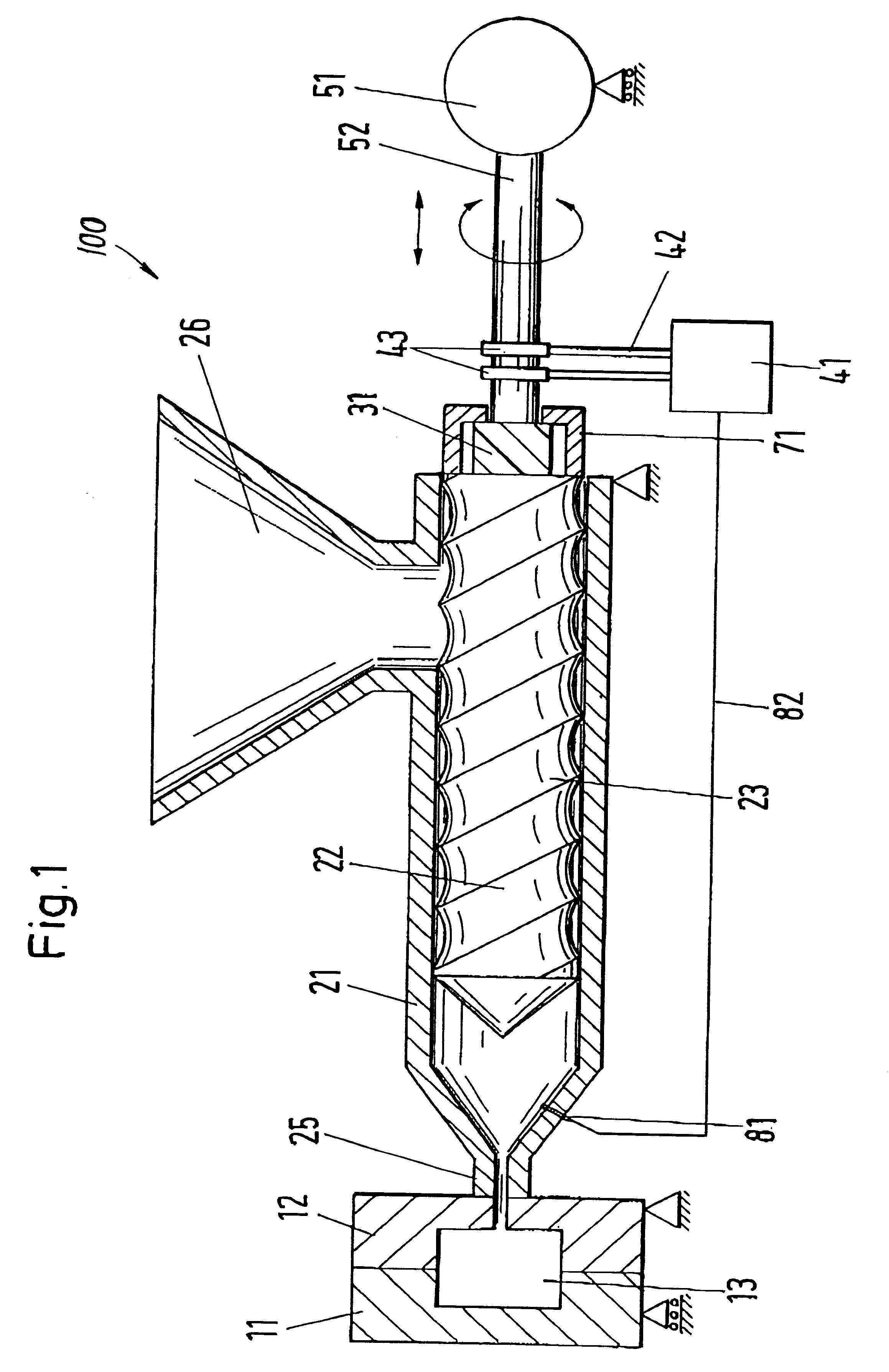
Referring to FIG. 1, an injection molding machine 100 according to an embodiment of the invention includes a movable mold part 11 and a fixed mold part 12 form a mold cavity 13. The fixed mold part 12 is connected to an injection nozzle 25 of an injection molding cylinder 21. A material supply 26 is mounted on the injection molding cylinder 21. A material conveyance unit 22 is arranged in the injection molding cylinder 21 and connected via a driving rod 52 to a drive 51. A thermal sensor 81 is mounted on the injection molding cylinder 21 and connected via a measurement line 82 to a frequency generator 41.

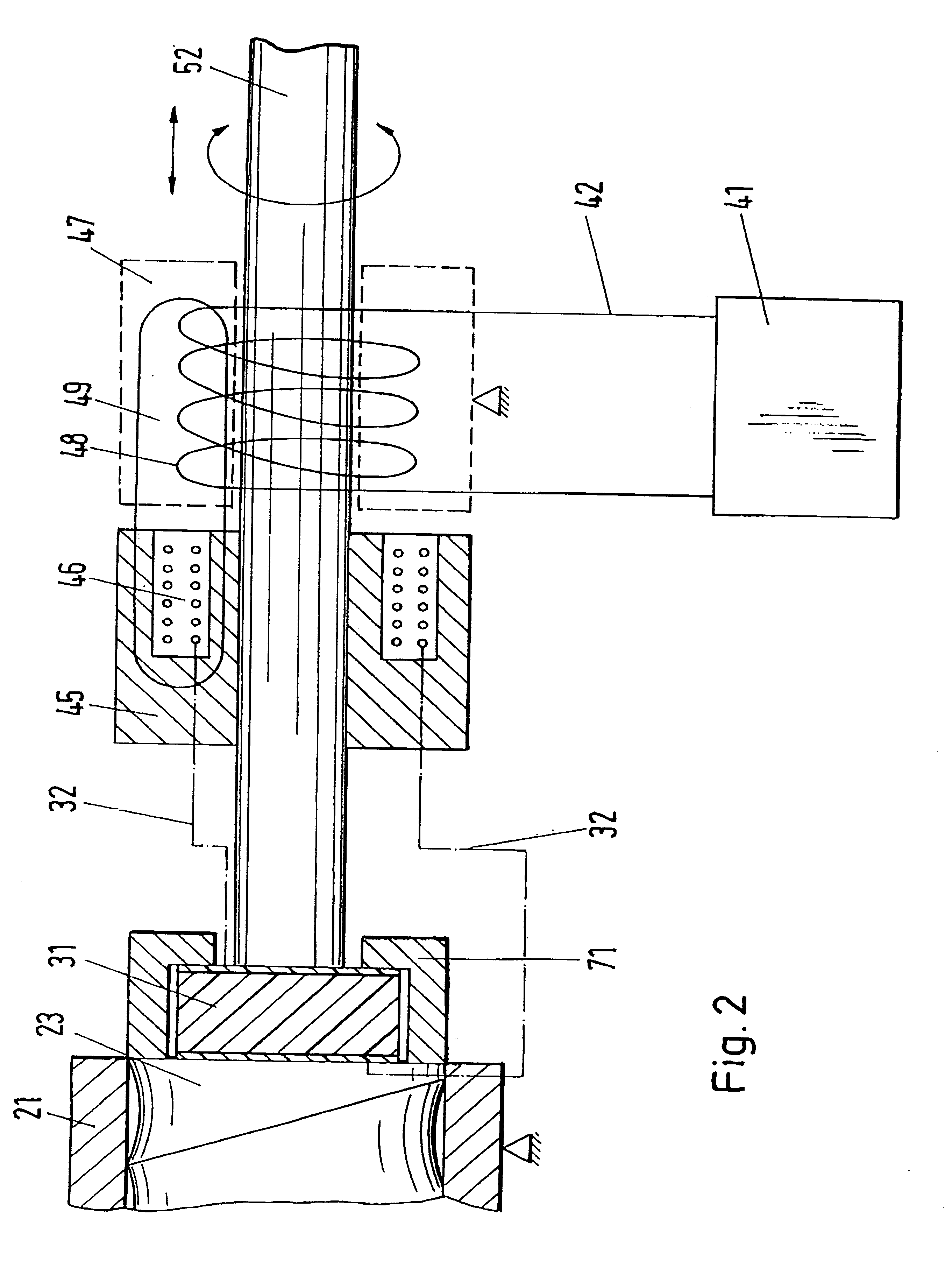
The material conveyance unit 22 is embodied as a screw 23 in FIG. 1. A housing 71 attached at the foot end of the material conveyance unit 22 encompasses a vibration element 31. The vibration element 31 is connected to the driving rod 52, which is attached to the drive 51. Loop contacts 43 on the driving rod 52 are corrected via a corniection 42 to the frequency generator 41.

The vib...


PUM

PropertyMeasurementUnit
Frequencyaaaaaaaaaa
Temperatureaaaaaaaaaa
Lengthaaaaaaaaaa

Abstract

An injection molding machine includes an injection molding cylinder with a material supply at one end and an injection nozzle at the other end and a material conveyance unit attached to a drive and movable in the injection molding cylinder. The injection molding machine also includes a vibration element for inducing a flow of melt within the injection molding cylinder for homogenizing the melt.

Description

1. Field of the InventionThe invention relates to an injection molding machine having an injection molding cylinder with a funnel-shaped material supply at a foot end of the injection molding cylinder and an injection nozzle corresponding to a mold at a head of the injection molding cylinder and a material conveyance unit attached to a drive and movable at least in the interior of the injection molding cylinder. The invention also relates to a process for guiding a melt through such an injection molding cylinder.2. Description of the Related ArtGerman reference DE-Gbm 91 06 039 discloses a gum massage brush with a handle, wherein the final, finished shape of the brush is attained by folding a known plastic along two folding axes by local softening, for example, by ultrasound. Thus, according to the aforementioned document, the finished part is treated by ultrasound, but the plastic mass in the injection molding machine is not.Usually, a plastic melt is mixed in the injection molding...

Claims


Application Information

Patent Timeline
IPC IPC(8): B29C45/58B29C45/46
CPCB29C45/585
Inventor GRUNITZ, OTTO
Owner ATECS MANNESMANN GMBH
Why Eureka
Try Eureka