Multiple power source system and apparatus, motor driving apparatus, and hybrid vehicle with multiple power source system mounted thereon

a technology of multiple power sources and power sources, which is applied in the direction of generator control by field variation, gas pressure propulsion mounting, dynamo-electric motors/converters, etc., can solve the problems of apparatus having the plurality of power sources not working properly, apparatus being undesired bulky, etc., to simplify the structure of multiple power sources and simplify the structure of an apparatus

Inactive Publication Date: 2002-11-05
TOYOTA JIDOSHA KK
View PDF15 Cites 154 Cited by
  • Summary
  • Abstract
  • Description
  • Claims
  • Application Information

AI Technical Summary

Benefits of technology

is thus to simplify the structure of a multiple power source system having a plurality of power sources for driving a three-phase motor,

Problems solved by technology

This makes the structure of the apparatus rather complicated.
These structures, however, make the apparatus undesirably bulky.
The apparatus having the plurality of power sources may not work properly when either one of the high voltage power source and the low voltage power source has an insufficiency of electric power.
This undesirably increases the required number of electric parts and makes the power source circuit rather complicated, thereby increasing the manufacturing cost and lowering the reliability.
Even the step-up and step-down circuit, which is provided only for the emerg

Method used


Image

  • Multiple power source system and apparatus, motor driving apparatus, and hybrid vehicle with multiple power source system mounted thereon
  • Multiple power source system and apparatus, motor driving apparatus, and hybrid vehicle with multiple power source system mounted thereon
  • Multiple power source system and apparatus, motor driving apparatus, and hybrid vehicle with multiple power source system mounted thereon

Examples


first embodiment

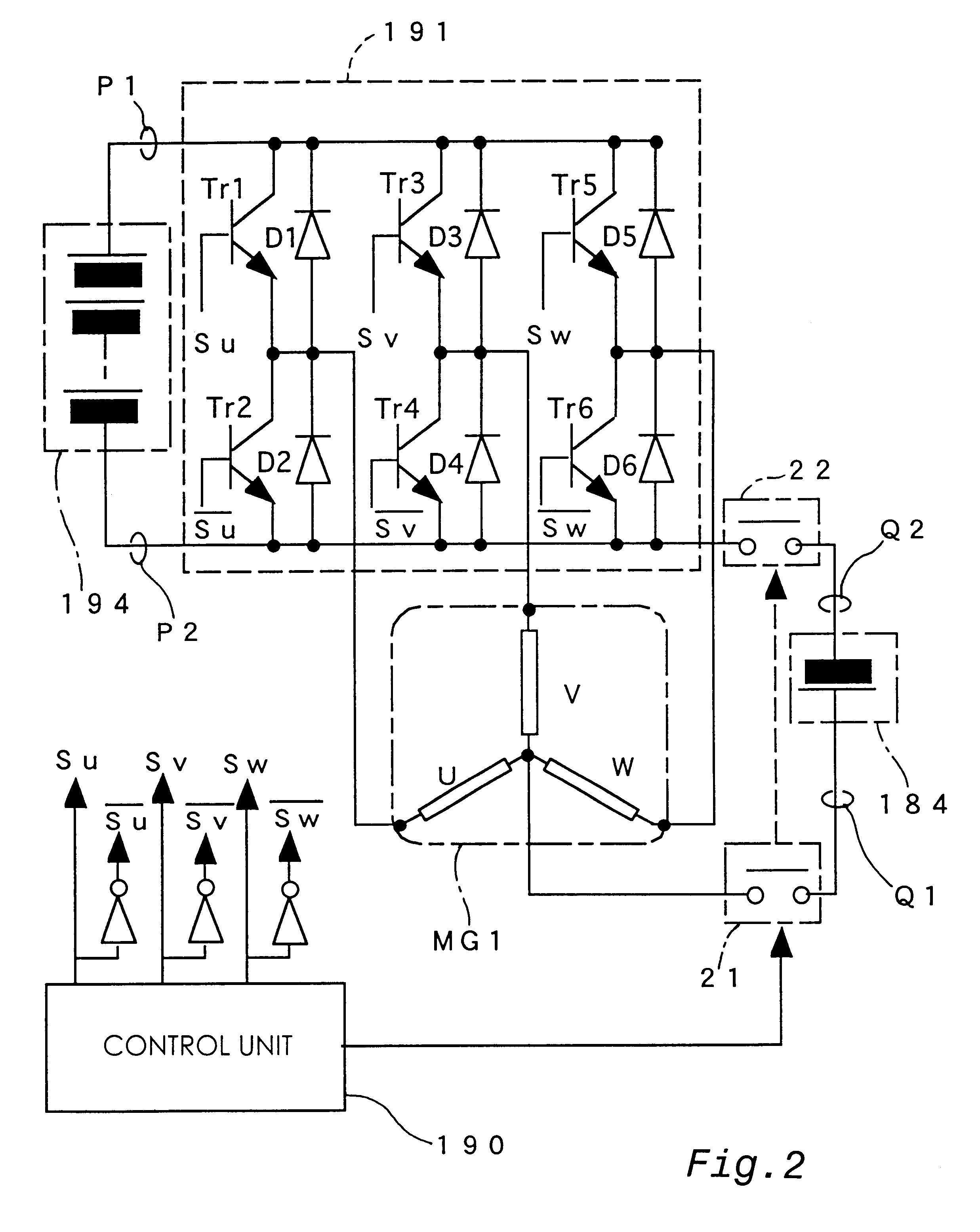
In the description of the first embodiment, the U-phase coil of the first motor MG1 is used as the reactance, in which the electric power for the voltage step-up is accumulated in the form of magnetic energy. Similarly the V-phase coil and the W-phase coil may be used as the reactance. In the case of the V-phase coil, the transistor Tr4 is turned on and off, and the high voltage battery 194 is charged via the diode D3. In the case of the W-phase coil, the transistor Tr6 is turned on and off, and the high voltage battery 194 is charged via the diode D5. The electric current flowing through each phase does not have any contribution to the revolving magnetic field in the first motor MG1. The supply of electricity to each phase coil accordingly does not cause rotation of the first motor MG1. Similarly any of the three-phase coils of the second motor MG2 may also be used as the reactance.

In the embodiment discussed above, the motor MG1 has the Y-connected three-phase coils. The principle...

second embodiment

(6) Second Embodiment

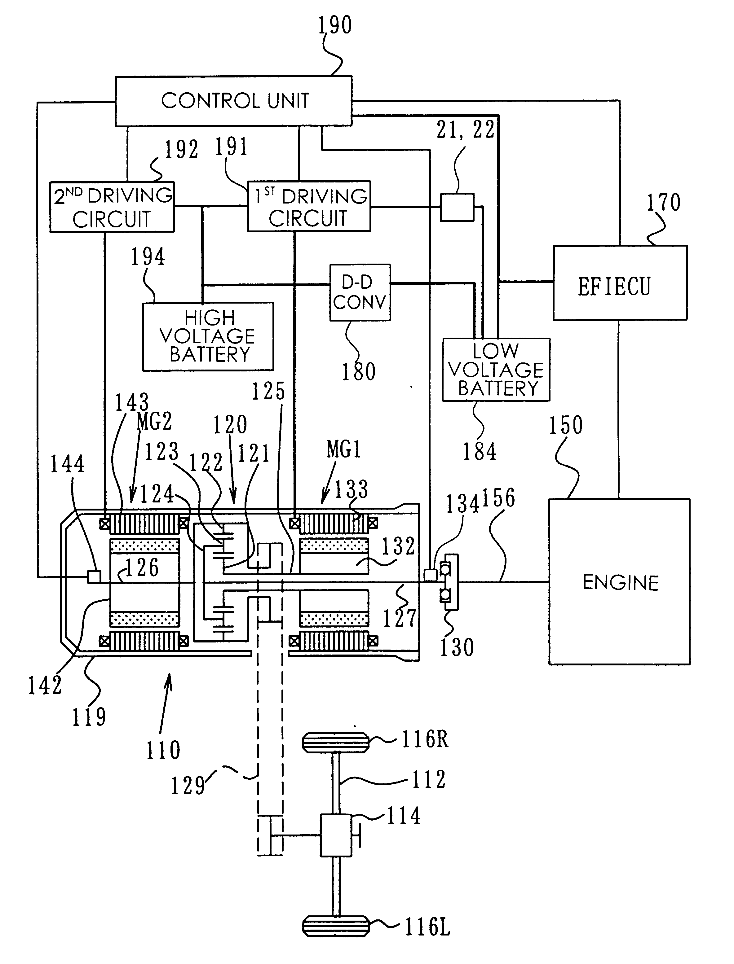
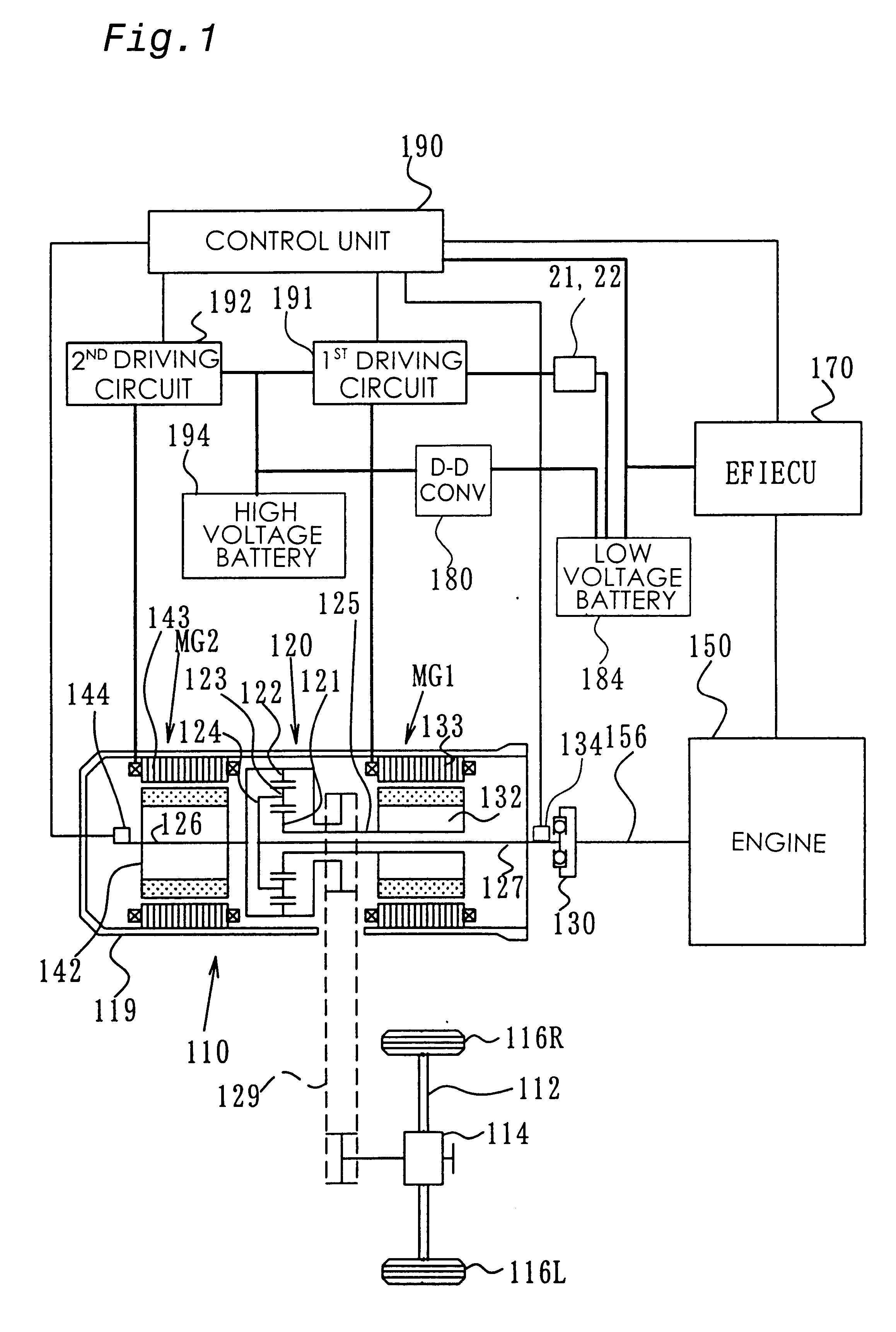
The following describes a motor driving apparatus with a multiple power source system incorporated therein as a second embodiment according to the present invention. The motor driving apparatus of the second embodiment is mounted on the hybrid vehicle shown in FIG. 1. The structure of the second embodiment is similar to that of the first embodiment, except the following two points:

(1) a fuel cell stack 384 (see FIG. 8) is provided, in place of the low voltage battery 184; and

(2) the control unit 190 carries out a different control procedure.

The structure of the electric circuit in the second embodiment is not specifically illustrated here. In the second embodiment, the output voltage of the fuel cell stack 384 is set to be lower than the output voltage of the high voltage battery 194. The electric current accordingly does not flow from the fuel cell stack 384 into the high voltage battery 194 through the flywheel diodes D1 through D6.

FIG. 6 is a flowchart showin...


PUM


Abstract

In a multiple power source system of the present invention that has an inverter connected to a reactance, such as three-phase coils in a motor, a high voltage battery is connected with a low voltage battery via one transistor (Tr2) and one diode (D2) included in the inverter and one phase coil (U-phase coil) of the three-phase motor. The transistor Tr2 is turned on to make the electric current flow from the low voltage battery to the U-phase coil. The transistor Tr2 is subsequently turned off at a preset timing, so that the electric energy accumulated in the reactance, that is, the U-phase coil, flows through the diode D1 into the high voltage battery and thereby charges the high voltage battery. This arrangement enables the charging process from the low voltage battery to the high voltage battery without any complicated circuit structure for the voltage step-up. The three-phase motor may be unipolar driven with transistors connected to one side of the inverter. The arrangement of the present invention does not require any complicated structure, which undesirably increases the size of the multiple power source system, in order to ensure mutual supplement of the electric energy between electric systems having a large difference in voltage, for example, an electric system for driving a hybrid vehicle and an electric system for its control circuit.

Description

1. Field of the InventionThe present invention relates to a multiple power source system that includes both a high tension electric system driven by high tension electric energy and a low tension electric system driven by lower tension electric energy. More specifically the invention pertains to a multiple power source system that compensates for an insufficiency of electric energy in a certain electric system, as well as to an apparatus and a vehicle with the multiple power source system mounted thereon.2. Description of the Related ArtElectric energy is usable in a wide range of technical fields including thermal, optical, power-driven, and data communication, and is used as the energy power source of various industries. Each apparatus utilizing the electric energy has predetermined ratings and ensures the normal operations under predetermined rated voltage and power. A typical industrial apparatus includes a plurality of devices having different rated voltages and a plurality of ...

Claims


Application Information

Patent Timeline
IPC IPC(8): B60L11/12B60K6/00B60L11/00B60K6/04B60L11/02B60K6/20H02J7/00B60K6/26B60K6/28B60K6/445B60L50/15B60L50/16B60W10/08B60W10/26B60W10/30B60W20/00F02D29/02H01M10/44H02M7/5387H02P27/06
CPCB60K6/26B60K6/28B60K6/445B60L11/005B60L11/123B60L11/14B60L15/007B60W10/08B60W10/26B60W10/30H02P2209/01Y02T10/6217Y02T10/7005Y02T10/7022Y02T10/7077Y10S903/903Y10S903/906Y10S903/907Y02T10/642Y02T10/6239B60L50/40B60L50/61B60L50/16Y02T10/62Y02T10/64Y02T10/70Y02T10/7072
Inventor SASAKI, SHOICHI
Owner TOYOTA JIDOSHA KK
Why Eureka
Try Eureka