
Mosquito killing system
a technology for killing systems and mosquitoes, which is applied in the field of portable insect killing devices, can solve the problems of inability of the grid to electrocute additional insects, short circuits, and ineffective prior art devices for killing mosquitoes
- Summary
- Abstract
- Description
- Claims
- Application Information
AI Technical Summary
Problems solved by technology
Method used
Image

Examples
Embodiment Construction
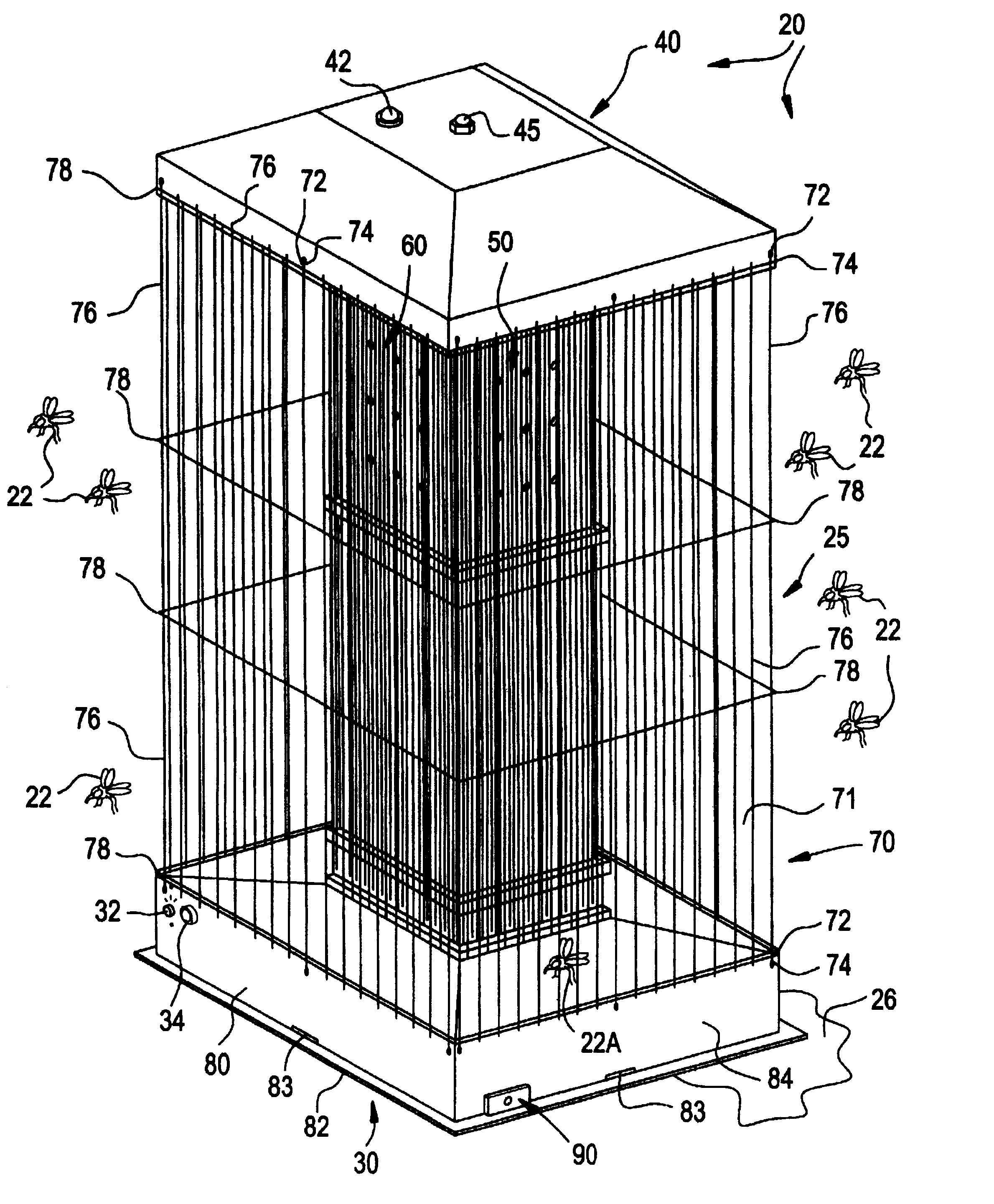
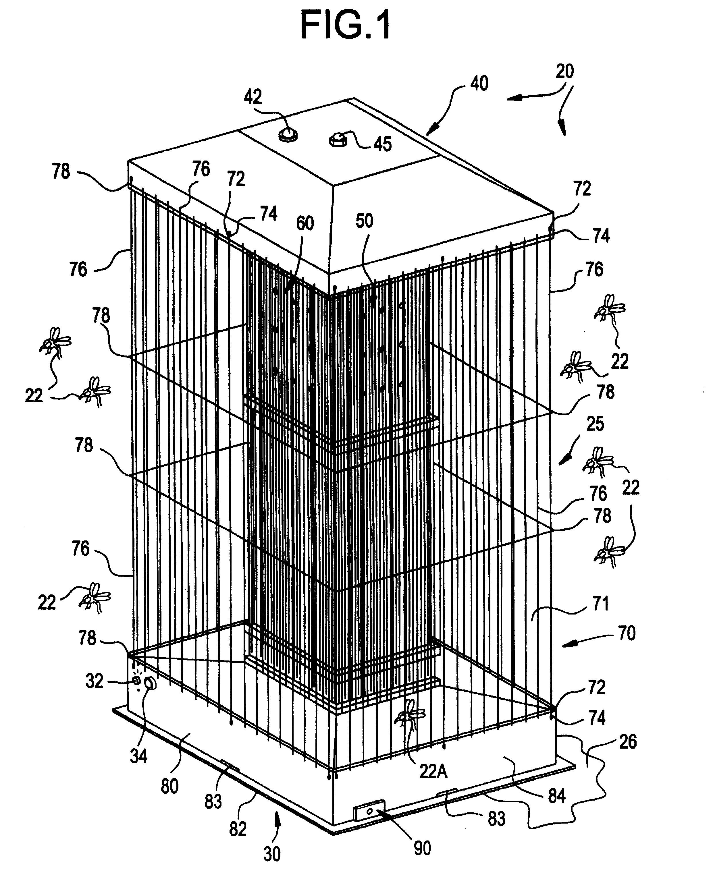
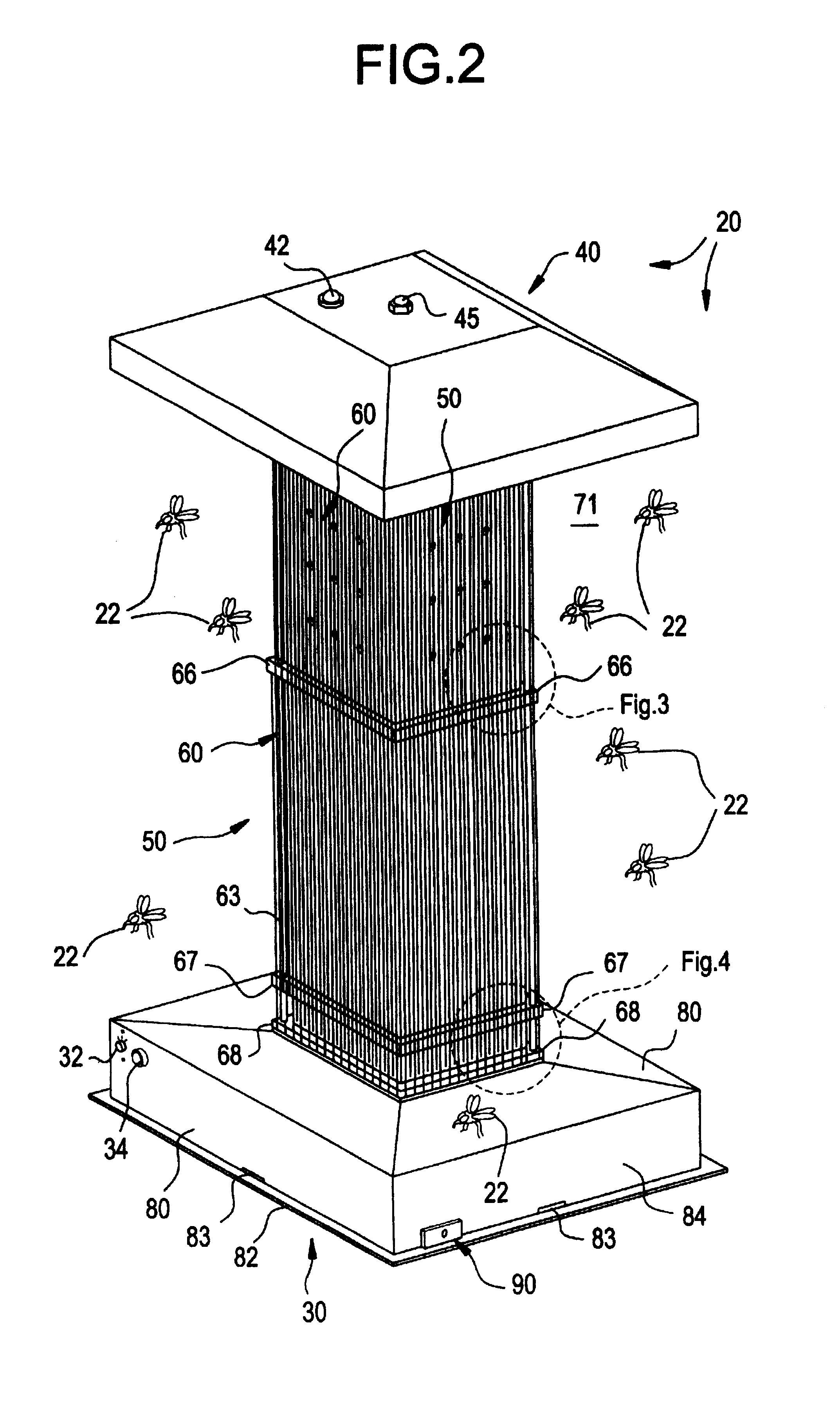
Referring more specifically to the drawings, my improved mosquito killing system is generally designated by reference numeral 20. System 20 attracts mosquitoes 22 by actively projecting multiple infrared heat gradients and pressure differentials coupled with a wide variety of aromatics that stimulate animal body heat and breathing.
In the best mode, system 20 comprises an elongated, generally parallelepiped housing 25 disposed upon a convenient supporting surface 26 (FIG. 1). The housing comprises a rectangular support base 30 and a spaced apart, truncated pyramidal roof 40 (FIGS. 1-2). The roof closes the tower interior. A switch 32 and photoelectric sensor system 34 control system operation, as discussed hereinafter. A pilot light 42 physically protrudes from roof 40 to indicate the operational status of system 20.
The roof 40 is secured to an internal heating tower 50 extending between the base 30 and the roof 40. A conventional bolt 45 extends through roof 40 to mate with a conven...
PUM
 Abstract
Description
Claims
Application Information