Data synchronizing signal detector, signal processing device using the detector, information recording and reproducing apparatus having the detector and the device, data synchronizing signal detecting method, and information recording medium for using in the method

a data synchronization signal and detector technology, applied in the direction of synchronizing signal speed/phase control, digital signal error detection/correction, instruments, etc., can solve the problems of data sync signal detection performance cannot be improved, and the whole error rate is extremely deteriorated, so as to improve the detection rate and improve the accuracy

Inactive Publication Date: 2004-09-14
HITACHI GLOBAL STORAGE TECH JAPAN LTD +1
View PDF10 Cites 42 Cited by
  • Summary
  • Abstract
  • Description
  • Claims
  • Application Information

AI Technical Summary

Benefits of technology

is to detect the data sync signal with higher accuracy and thereby to improve the detection rate.
According to a first aspect of the invention, there is provided an information recording and reproducing apparatus comprising a data discriminator including data discrimination means and sync signal discrimination means, wherein the detection of the data sync signal is carried out for a discriminated bit string output from the sync signal discrimination means while at the same time carrying out the data demodulation for a discriminated bit string output from the data discrimination means. As a result, the discrimination of the data sync signal and the data reproduction and demodulation can be carried out in the way most suitable for each of the data sync signal and the data. Thus, an accurate data sync signal detection with only a small amount of error is made possible, and the detection performance of the data sync signal can be improved while maintaining the data discrimination performance. In the case where the Viterbi decoder is used as the data discrimination means and the sync signal discrimination means for optimization described above, the number of states, the number of paths for state transition and the path memory length can be optimized.
According to a second aspect of the invention, there is provided an information recording and reproducing apparatus comprising a single (shared) data discrimination means, wherein the configuration of the data discrimination means is switched thereby to switch the discrimination characteristic using the data sync signal detection output obtained by data sync signal detection. With this configuration, the circuit size can be reduced. Also, during the data sync signal detection and the data demodulation following the data sync signal, the discrimination means is temporally optimized in a form suitable for the data sync signal discrimination and detection on the one hand and the data reproduction and demodulation on the other hand, respectively. In this way, the detection performance of the data sync signal can be improved while maintaining the data discrimination performance. Further, using a Viterbi decoder as data discrimination means, the configuration can be switched to optimize the number of states, the number of paths for state transition and the path memory length for each of data discrimination and sync signal discrimination.
Furthermore, delay means for delaying the input data to the data discrimination means can be provided to apply the output of the delay means to the data discrimination means by the sync signal detection signal output from the data sync signal detection means. This configuration makes it possible to effectively use the data corresponding to the delay time required for discrimination in the data discrimination means when switching the configuration of the data discrimination means.
According to a third aspect of the invention, in order to eliminate the path convergence pattern, the head of the data section following the data sync signal is coded by a first data coding scheme coincident with the limitation of the signal string of the data sync signal and recorded and reproduced in and from the information recording medium, while the remaining data are coded by a second data coding scheme for improving the data recording and reproduction performance, and recorded and reproduced in and from the information recording medium. Also in this case, the use of a Viterbi decoder as data discrimination means makes it possible to optimize the number of states, the number of paths for state transition and the path memory length for each of the data discrimination means and the sync signal discrimination means or each of the time for the data discriminating operation and the sync signal discriminating operation.
According to a fourth aspect of the invention, the characteristics of a low-pass filter and the equalizing means providing signal processing means are switched to optimized ones for the sync signal and the data by the sync signal detection output. Also in this case, wasteful data can be reduced by providing delay means in the input portion of the equalizing means for delaying the input signal of the equalizing means and inputting the output of the delay means to the equalizing means by the sync signal detection signal output from the data sync signal detection means.

Problems solved by technology

Even in the case where the data decoded in the data section 78 has a very good error rate, a detection error (i.e. failure to detect at the right position or detection at a wrong position) of the data sync signal 77 which is normally about several bytes will lead to the failure to correctly decode the subsequent data section 78 which lasts several tens of bytes to several hundred bytes, thereby extremely deteriorating the whole error rate.
Thus, the bit interval is required to be reduced as compared with other codes of high code rate for recording the same amount of information, and therefore the performance cannot be improved.
In this method, however, although the accuracy can be improved for the bit sync (i.e. the clock reproduction) for the data, the detection performance of the data sync signal cannot be improved in view of the fact that the data sync signal is detected by detecting the data start position in the same state of the Viterbi decoder as when the data portion is detected.

Method used


Image

  • Data synchronizing signal detector, signal processing device using the detector, information recording and reproducing apparatus having the detector and the device, data synchronizing signal detecting method, and information recording medium for using in the method
  • Data synchronizing signal detector, signal processing device using the detector, information recording and reproducing apparatus having the detector and the device, data synchronizing signal detecting method, and information recording medium for using in the method
  • Data synchronizing signal detector, signal processing device using the detector, information recording and reproducing apparatus having the detector and the device, data synchronizing signal detecting method, and information recording medium for using in the method

Examples


first embodiment

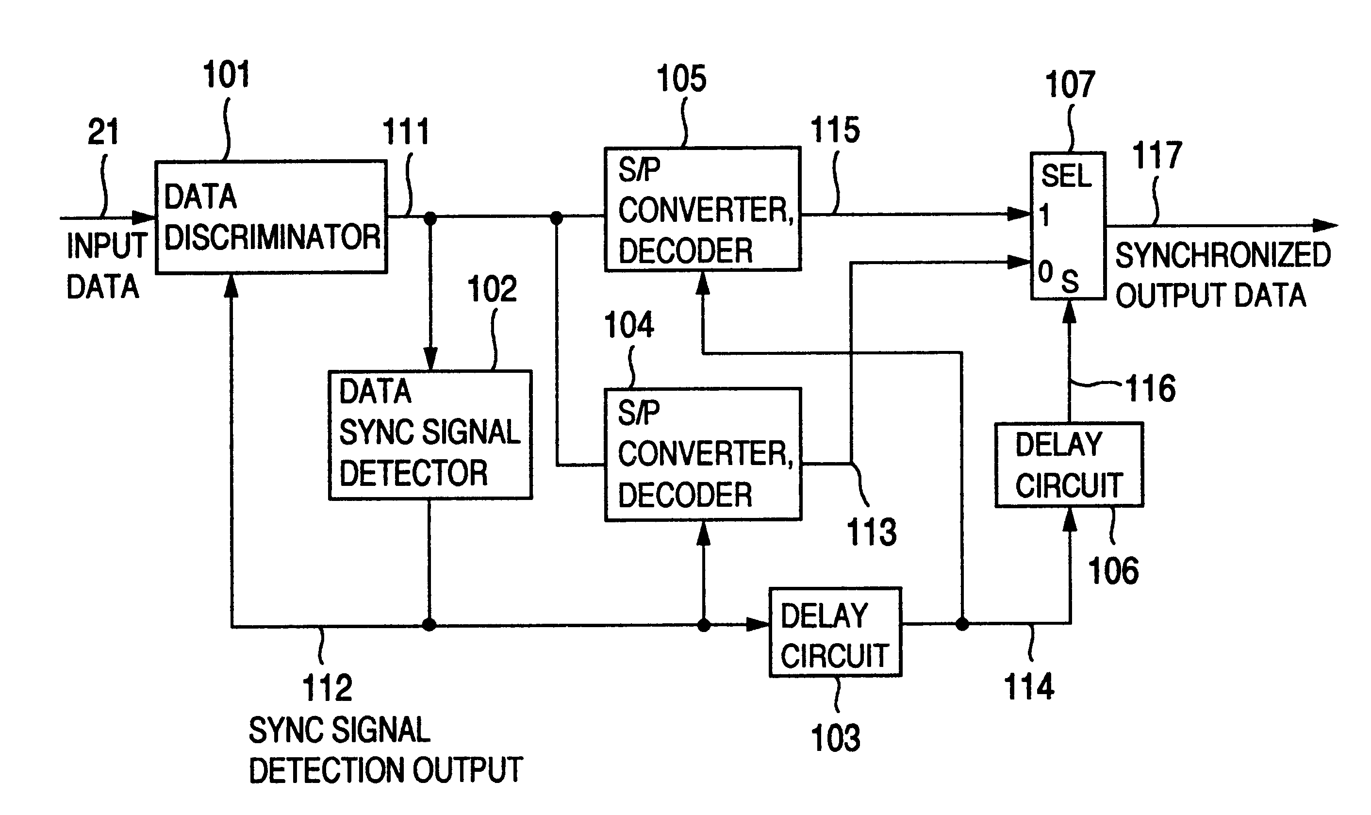
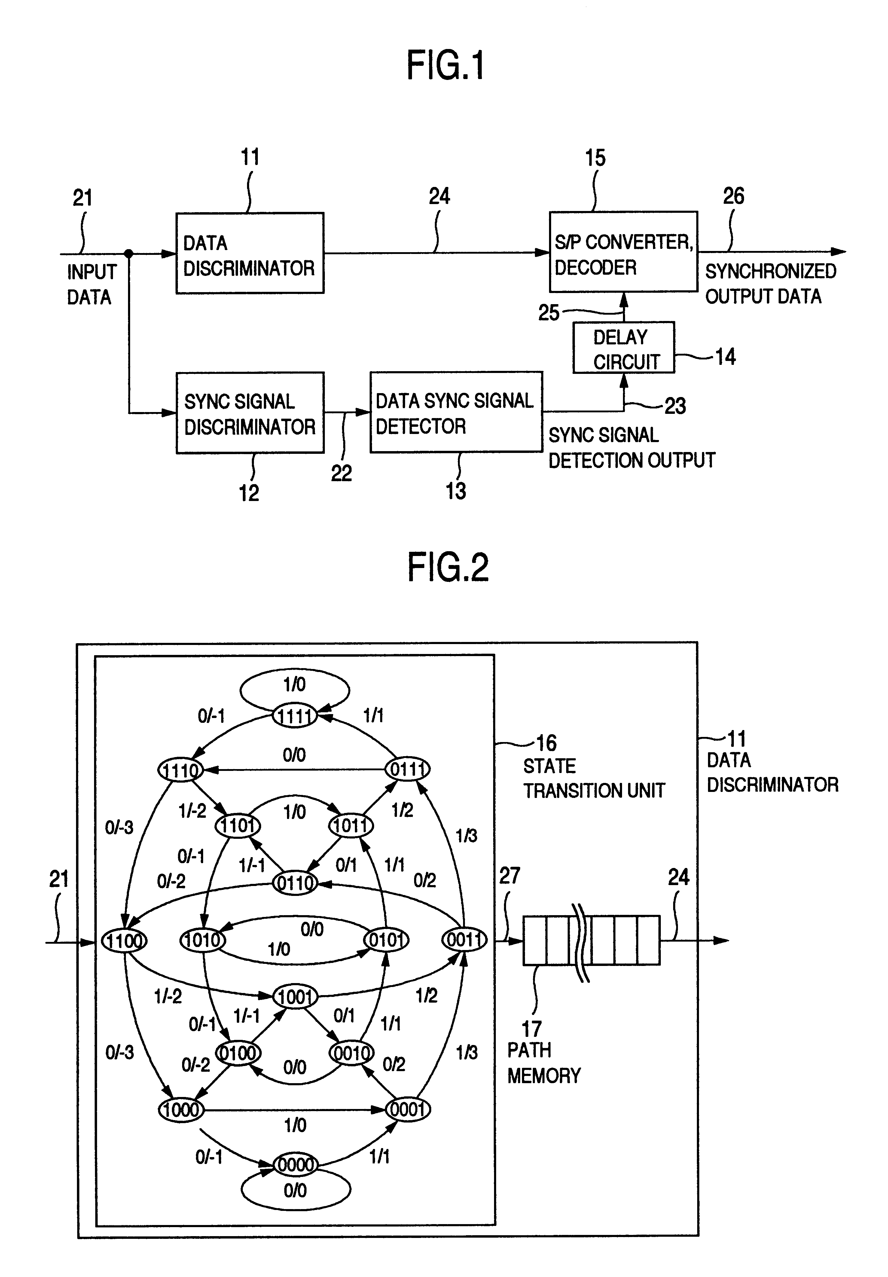
A data sync signal detector according to the invention will be explained with reference to FIGS. 1 to 5. First, in the data sync signal detector shown in FIG. 1, input data 21 are input to a data discriminator 11 and a sync signal discriminator 12. The data discriminator 11 discriminates the data in the input data 21 and produces a data discrimination output 24 as a discriminated code bit output. The sync signal discriminator 12 processes the input data 21 for data discrimination and produces a sync signal discrimination output 22 as a discriminated code bit output. A data sync signal detector 13 is supplied with the sync signal discrimination output 22, detects the data sync signal in the input data 21 and produces a sync signal detection output 23. The conventional method can be applied directly to the detection of the data sync signal in the data sync signal detector 13.

A delay circuit 14 delays the sync signal detection output 23 by a predetermined length of time and outputs a s...

second embodiment

the invention also uses the data format shown in FIG. 4. The data sync signal 31 further has the function of absorbing the effect of the discrimination error which may be caused in the data discriminator 43 according to the input data select output 48 switched discontinuously by the signal selector 42 regardless of the original reproduced signal upon detection of the sync signal detection output 50.

FIG. 8, like FIG. 5, shows an example of signals produced at various parts in the configuration according to the second embodiment of the invention shown in FIG. 6. The numerals in the left portion of the drawing are coincident with the numbers of the signals produced at various parts of FIG. 6, and the apparatus according to the second embodiment operates on this time chart.

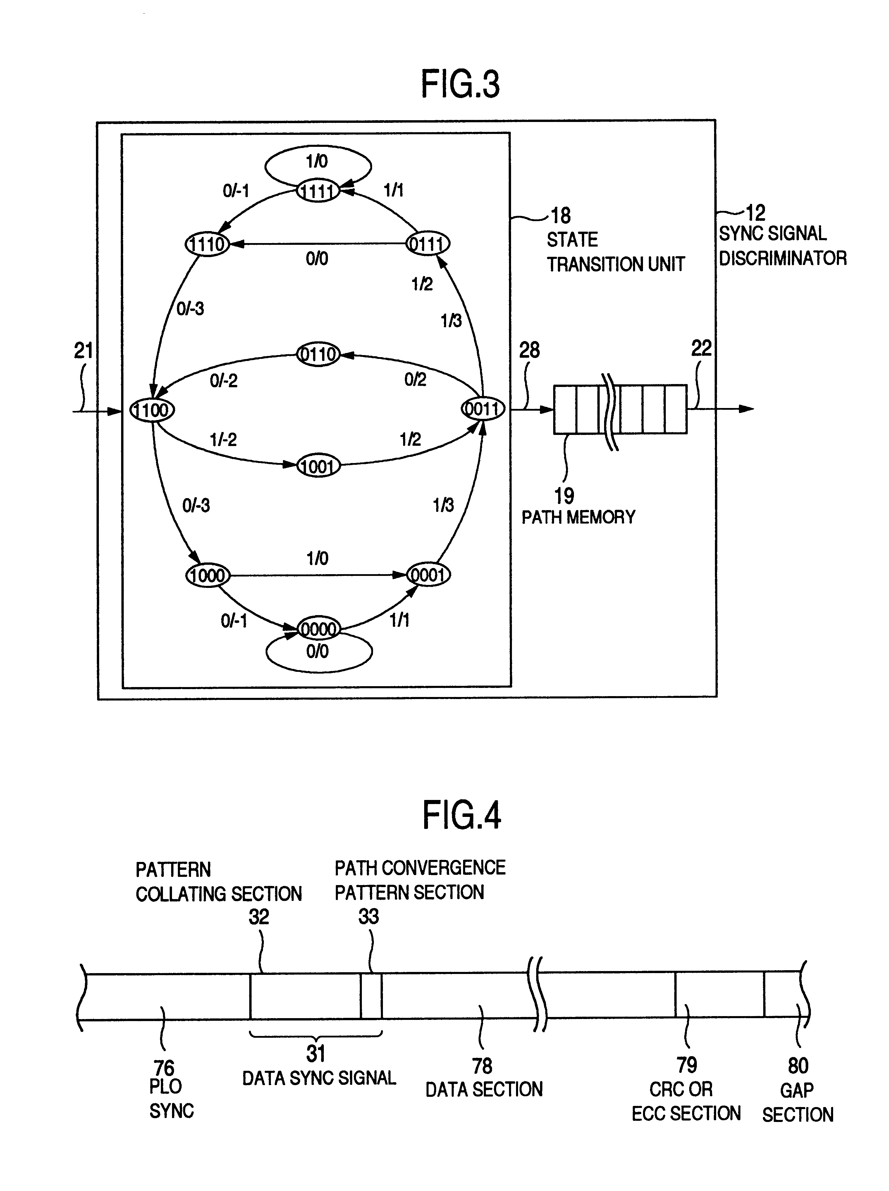
First, in the input data 21, "PLO" is a signal portion corresponding to the PLO sync section 76 in FIG. 4, "SYNC" a signal portion corresponding to the data sync signal 31 of FIG. 4, and "Data" a signal portion corres...

third embodiment

The third embodiment also uses the data format shown in FIG. 4 and has the same function as the second embodiment. FIG. 11, like FIG. 5, shows examples of signals produced at various parts in the configuration of the invention shown in FIG. 9. The numerals in the left portion of the drawing coincide with the numbers of the signals produced at the various parts in FIG. 9, and the third embodiment operates on the time chart as shown in FIG. 11.

First, in the input data 21, "PLO" indicates a signal portion corresponding to a PLO sync section 76, "SYNC" a signal portion corresponding to a data sync signal 31, and "Data" a signal portion corresponding to a data section 78. Then comes an input data delay output 87 delayed by the delay circuit 81. This is followed by an input data select output 88 selected by the signal selector 82. The position where the signal is switched discontinuously by the sync signal detection output 90 regardless of the original reproduced signal is indicated by ar...


PUM

PropertyMeasurementUnit
length of timeaaaaaaaaaa
unit storage areaaaaaaaaaaa
delay timeaaaaaaaaaa

Abstract

A data discriminating unit includes a data discriminator and a sync signal discriminator. A data sync signal is detected for the bit string discriminated from the output of the sync signal discriminator, and the data is demodulated for the bit string discriminated from the output of the data discriminator, thereby optimizing the signal to a form suitable for discrimination and detection of the data sync signal and demodulation for data reproduction. As a result, the detection performance of the data sync signal can be improved while maintaining the data discrimination performance. A Viterbi decoder is used for discrimination by the data discriminator and the sync signal discriminator for the optimization thereby to optimize the number of states, the number of paths for state transition and the path memory length. A signal having no continuous inversions of the recording data is used as the data sync signal.

Description

1. Field of the InventionThe present invention relates to an information recording and reproducing apparatus, or in particular to a technique for improving the detection rate of a data synchronizing (hereinafter referred to as "sync") signal by improving the performance of data discrimination of a data sync signal section.2. Description of the Related ArtFIG. 27 shows an example of the recording format in a magnetic disk device. Data are recorded or reproduced in and from each sector of a recording medium constituting a unit storage area. Each sector includes a PLO (phase locked oscillator) sync area 76 for pull-in of a PLL (phase locked loop), a data sync signal 77 for producing a decode timing signal for a modulated code by detecting the start position of the data, a data section 78 for actually recording and reproducing the data, and a CRC (cyclic redundancy check) or an ECC (error correcting code) 79 for detecting or correcting errors. A gap 80 constituting a pattern for absorbi...

Claims


Application Information

Patent Timeline
Patent Type & Authority Patents(United States)
IPC IPC(8): G11B27/30G11B20/10H04L1/00G11B27/10G11B5/012G11B5/09H04L7/04G11B20/14G11B20/18H04L7/08
CPCG11B20/10009G11B27/3027H04L1/0041H04L1/0047H04L1/0054G11B5/012G11B5/09G11B27/10H04L7/0008H04L7/04
Inventor WATANABE, YOSHIJUTAKASHI, TERUMI
Owner HITACHI GLOBAL STORAGE TECH JAPAN LTD
Why Eureka
Try Eureka