Illumination system and display device

a technology of illumination system and display device, which is applied in the field of illumination system, can solve the problems of fixed electromagnetic spectrum of light source, and achieve the effect of maximizing the contrast of images, and reducing the cost of production

Inactive Publication Date: 2005-01-11
KONINKLIJKE PHILIPS ELECTRONICS NV
View PDF14 Cites 79 Cited by
  • Summary
  • Abstract
  • Description
  • Claims
  • Application Information

AI Technical Summary

Benefits of technology

The amount of light emitted by the LEDs is set by varying the luminous flux of the light-emitting diodes. In general, this regulating of the luminous flux takes place in a very energy-efficient manner. For example, LEDs can be dimmed without an appreciable loss of light output. Preferably, the intensity of the light emitted by the low-pressure mercury-vapor discharge lamp and the light-emitting diodes is variable in response to the illumination level of an image to be displayed by the display device. Preferably, the color point of an image displayed by the display device is determined by the illumination system. By virtue thereof, an optimum contrast of the image to be displayed by the display device is achieved.
Preferably, each one of the light-emitting diodes has a luminous flux of at least 5 lm. LEDs having such a high output are also referred to as LED power packages. The use of these high-efficiency, high-output LEDs has the specific advantage that the number of LEDs necessary for a desired, comparatively high luminous output can be relatively small. This has a favorable effect on the compactness and the efficiency of the illumination system to be manufactured.

Problems solved by technology

A drawback of the known illumination system is that the light source has a fixed electromagnetic spectrum.

Method used


Image

  • Illumination system and display device
  • Illumination system and display device
  • Illumination system and display device

Examples


Embodiment Construction

The Figures are purely diagrammatic and are not drawn to scale. Particularly for clarity, some dimensions are exaggerated strongly. Where possible, like reference numerals refer to like parts in the drawings.

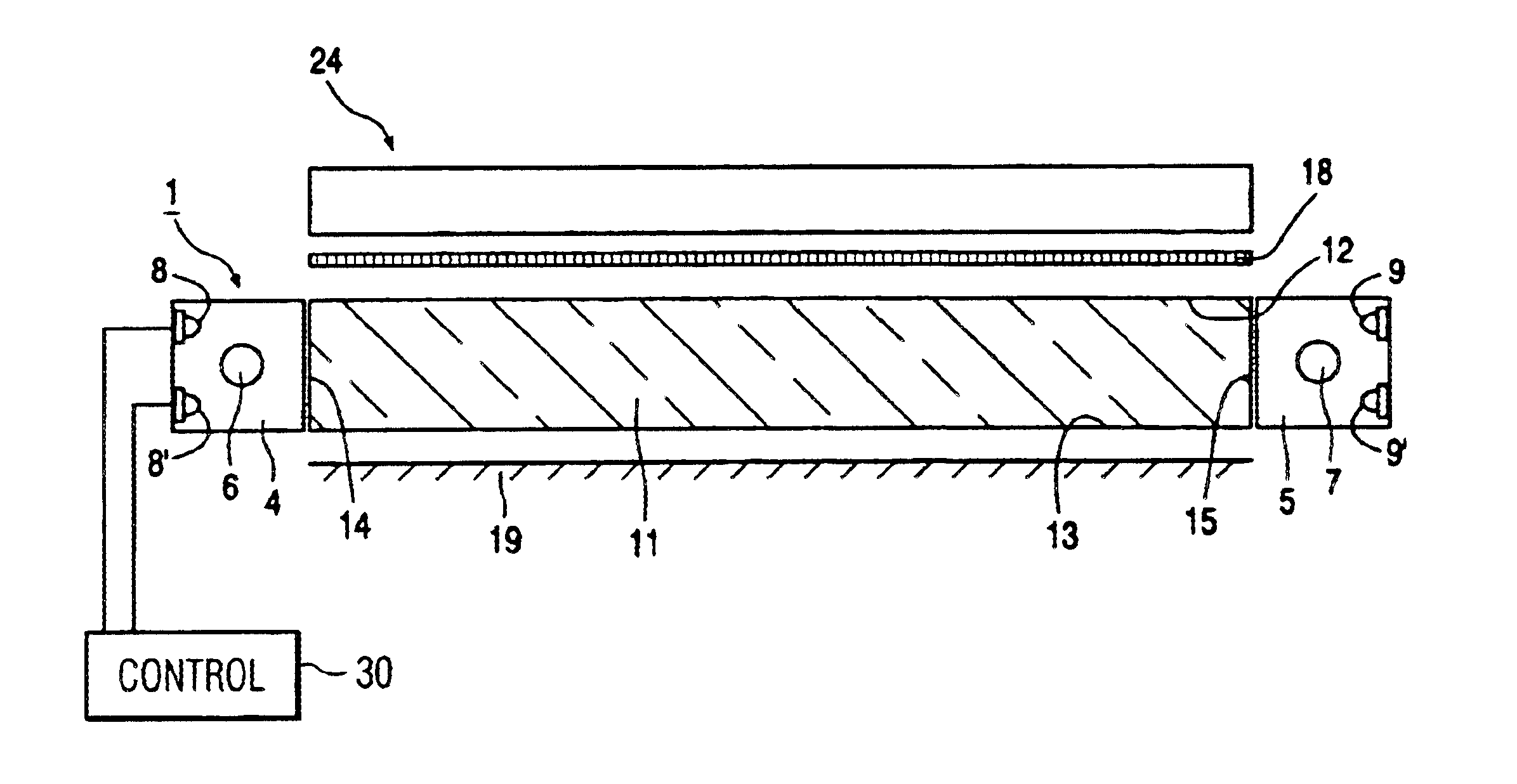
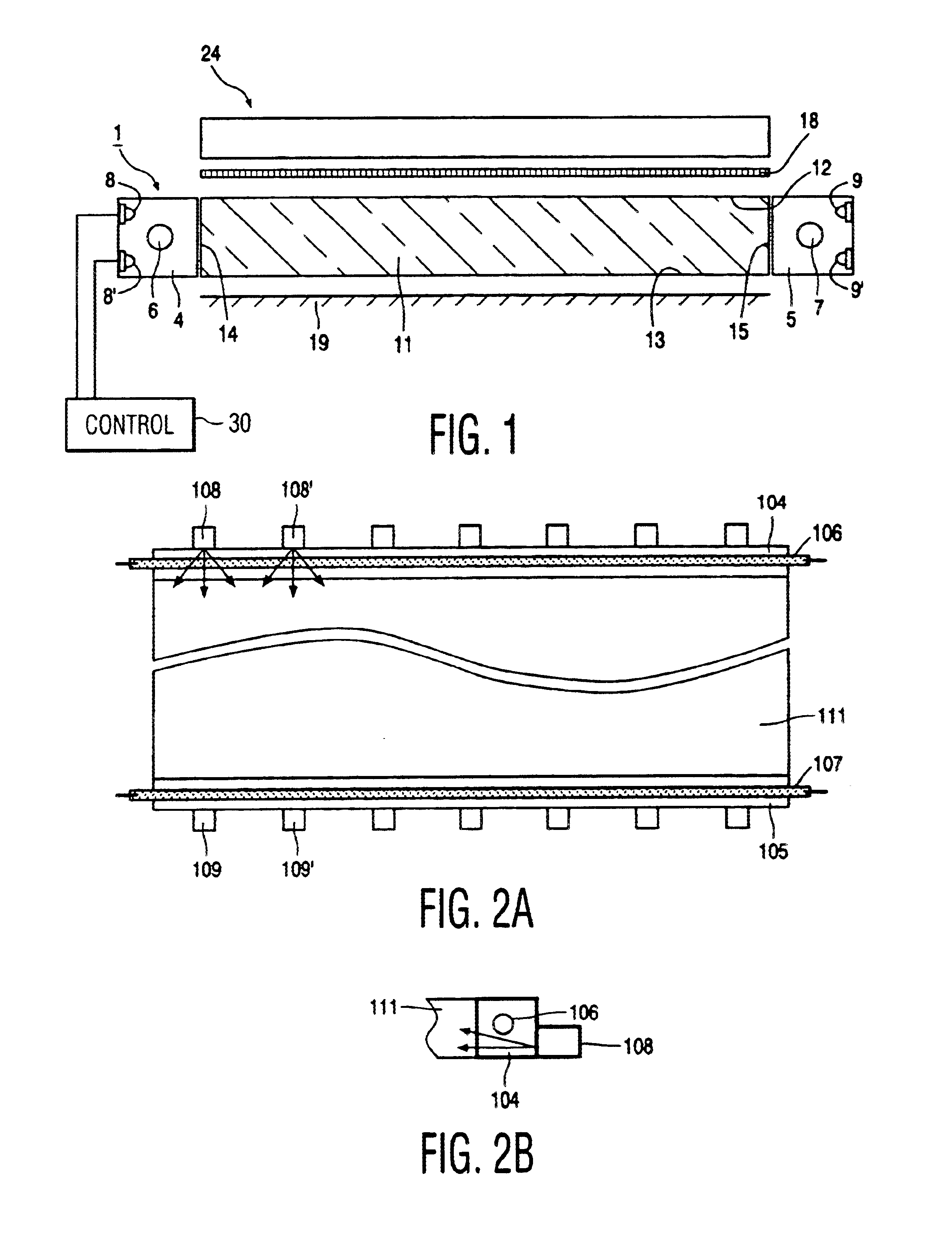
FIG. 1 is a very diagrammatic cross-sectional view of an example of a display device in accordance with the invention. The illumination system 1 comprises a light-emitting panel 11 of a light-transmitting material that is made of, for example, a synthetic resin, acryl, polycarbonate, PMMA, such as perspex, or of glass. Under the influence of total internal reflection, light is transported, in operation, through the panel 11. Said panel 11 has a front wall 12 and an opposite rear wall 13. Between the front wall 12 and the rear wall 13, light-transmitting edge surfaces 14, 15 for coupling light into the light-emitting panel 11 are situated on either side of the light-emitting panel. In the example of FIG. 1, the illumination system is provided with two light-mixing chambers 4; 5, ...


PUM


Abstract

A back lighting system for illuminating a display device comprises a light-emitting panel (1) and a light source (6) for coupling light into the light-emitting panel. The light source comprises a low-pressure discharge lamp (6; 7). The light source additionally comprises a plurality of LEDs (8, 8′, . . . ; 9, 9′, . . . ) for selectively setting the color temperature of the light emitted by the light source. Preferably, the LEDs increase the color temperature of the light emitted by the light source. Preferably, the light emitted by the back lighting system ranges from 6,000 to 10,500 K. Preferably, the LEDs are blue light emitting LEDs, each preferably having a luminous flux of at least 5 lm. The color point of an image to be displayed on a display screen of the display device is set by the back lighting system, thus enabling an optimum contrast to be achieved for the image to be displayed by the display device.

Description

BACKGROUND OF THE INVENTIONThis invention relates to an illumination system for illuminating a display device, comprising a light-emitting panel and a light source for coupling light into the light-emitting panel, said light source including a low-pressure mercury-vapor discharge lamp.The invention also relates to a display device comprising said illumination system.Such illumination systems are known per se and are also referred to as edge lighting systems. They are applied, inter alia, as back lighting for (image) display devices, for example for television receivers and monitors. Such illumination systems can particularly suitably be used as back lighting for non-emissive displays, such as liquid crystal display devices, also referred to as LCD panels, which are employed in (portable) computers or (cordless) telephones.Said display devices generally comprise a substrate provided with a regular pattern of picture elements (pixels), which are each controlled by at least one electro...

Claims


Application Information

Patent Timeline
Patent Type & Authority Patents(United States)
IPC IPC(8): F21V8/00F21Y101/02F21Y103/00
CPCG02B6/0068G02B6/005
Inventor CORNELISSEN, HUGO JOHANGREINER, HORSTCLARKE, JOHN ALFRED
Owner KONINKLIJKE PHILIPS ELECTRONICS NV
Why Eureka
Try Eureka