Communication port control module for lighting systems

Inactive Publication Date: 2005-01-18
KONINKLIJKE PHILIPS ELECTRONICS NV
View PDF20 Cites 29 Cited by
  • Summary
  • Abstract
  • Description
  • Claims
  • Application Information

AI Technical Summary

Benefits of technology

The separate device is implemented in hardware to perform error detection, noise filtering, and optionally other functions previously performed by the microprocessor, such as parallel to serial conversion, serial to parallel conversion, edge detection, arbitration control, and possibly others. The hardware device interposed between the lighting device and the control computer offloads much of the functionality from the microprocessor, providing faster operating speeds and permitting better use of less expensive microprocessors typically employed at such lighting devices. In a preferred embodiment, the serial to parallel conversion is implemented as a preshift register and a shift register, and the error detection is implemented in common hardware with serial to parallel conversion.

Problems solved by technology

One problem with prior art systems such as that of FIG. 1 is that for cost reasons, microprocessor 101 is typically a basic low end capability processor such as an 8051.
The tasks required to be performed by microprocessor 101 results in significant loading on the processor's limited capabilities, and decreased performance.

Method used


Image

  • Communication port control module for lighting systems
  • Communication port control module for lighting systems
  • Communication port control module for lighting systems

Examples


Embodiment Construction

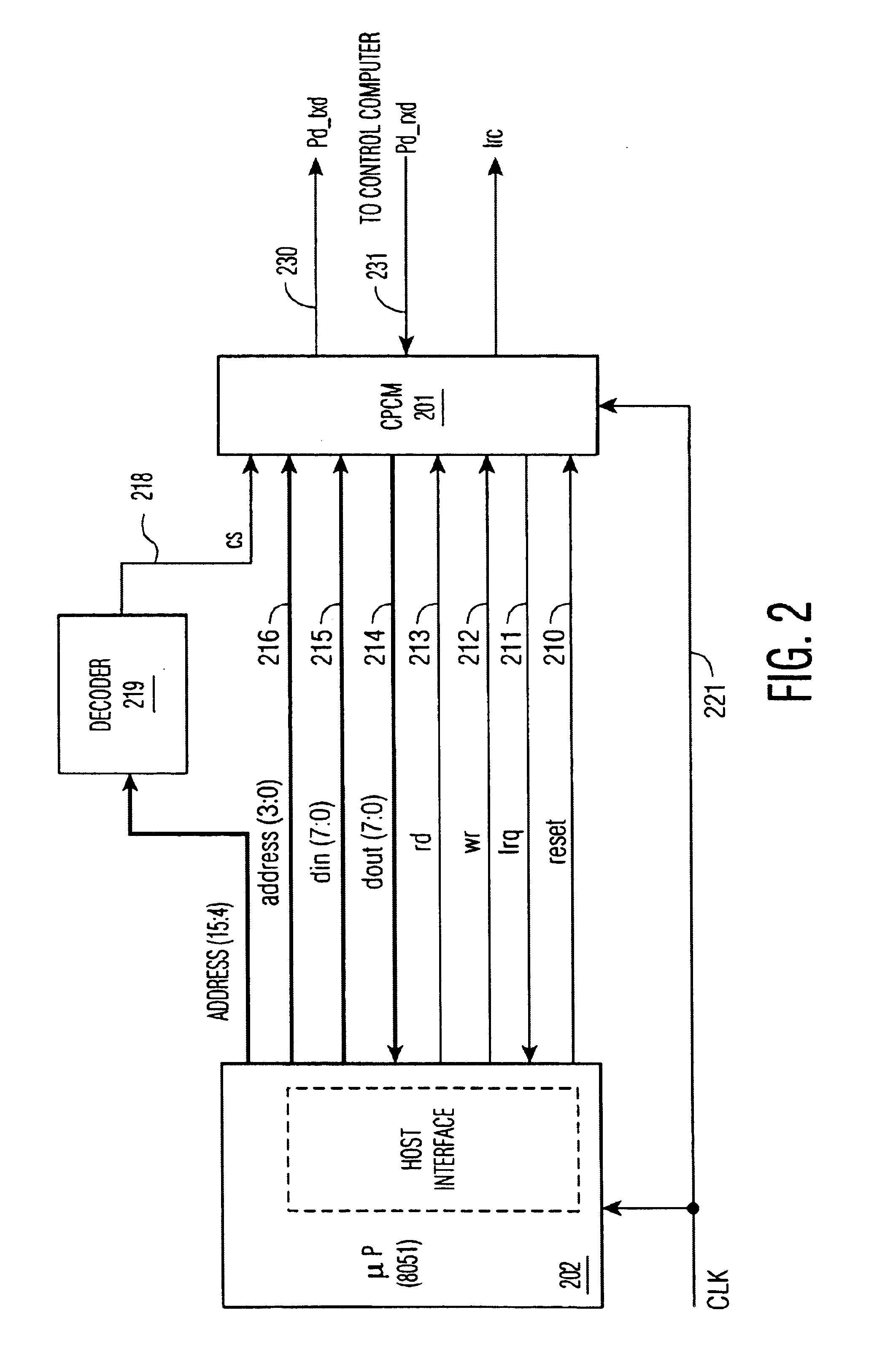
FIG. 2 depicts a block diagram of a hardware device CPCM 201 connected to a microprocessor 202. Not shown in FIG. 2 is the lighting device controlled by microprocessor 202. FIG. 2 includes a plurality of signals interfacing between CPCM 201 and microprocessor 202.

A decoder 219 and address lines 216 serve to permit communications to and from CPCM 201 over a parallel computer bus as is known in the art. More specifically, CPCM 201 is at a particular address known to microprocessor 202 and that address is asserted on the bus when communications with CPCM 201 are desired by the microprocessor. Several of the address lines are used for a chip select signal 218 and the remainder utilized as signal 216 in order to select the appropriate location within CPCM 201. Typically the most significant bits are utilized to decode as a chip select signal, and any remaining bits of the address are used to identify a location within the CPCM.

Signals 214 and 215 represent the data bus exchanging data be...


PUM


Abstract

An improved technique of interfacing a computer lighting device to a control computer is disclosed, wherein a hardware device is interposed between the control computer and the lighting device. The hardware device handles certain functions in hardware, thereby permitting the microprocessor at the lighting device to incur substantially less processing load.

Description

TECHNICAL FIELDThe present invention relates to lighting control networks, and more particularly, to an improved communication port control module (“CPCM”) that acts as a serial interface to a network control computer for a lighting system. The present invention also relates to a system that offloads much of the processing normally required of a microprocessor at the lighting device being controlled, instead performing such processing in hardware contained in an interface device interposed between the lighting device being controlled and the control computer controlling said lighting device.BACKGROUND OF THE INVENTIONCentralized lighting control systems are known in the art. Typically, the central computer controls the lighting system throughout a building or other facility, such as is defined by the DALI standard, a well-known lighting control standard. The lighting device being controlled interfaces to the central computer through a serial interface. A microprocessor at the lighti...

Claims


Application Information

Patent Timeline
IPC IPC(8): H05B37/02G06F5/00G06F13/36
CPCH05B37/0254H05B47/18
Inventor WANG, SHENGHONG
Owner KONINKLIJKE PHILIPS ELECTRONICS NV
Why Eureka
Try Eureka