Frequency divider system

Inactive Publication Date: 2005-01-25
BLACKBERRY LTD
View PDF4 Cites 23 Cited by
  • Summary
  • Abstract
  • Description
  • Claims
  • Application Information

AI Technical Summary

Benefits of technology

It is an object of the present invention to obviate or mitigate at least one disad

Problems solved by technology

Unfortunately, some components of an electronic device will only operate at a maximum frequency that is well below the desired system clock frequency.
It is not possible to include separate crystal oscillators in the electronic device because it is impractical to synchronize all the oscillators to the same system clock edges.
Furthermore, the addition of more crystal oscillators increases the size of the electronic device, an undesirable attribute of portable

Method used


Image

  • Frequency divider system
  • Frequency divider system
  • Frequency divider system

Examples


Embodiment Construction

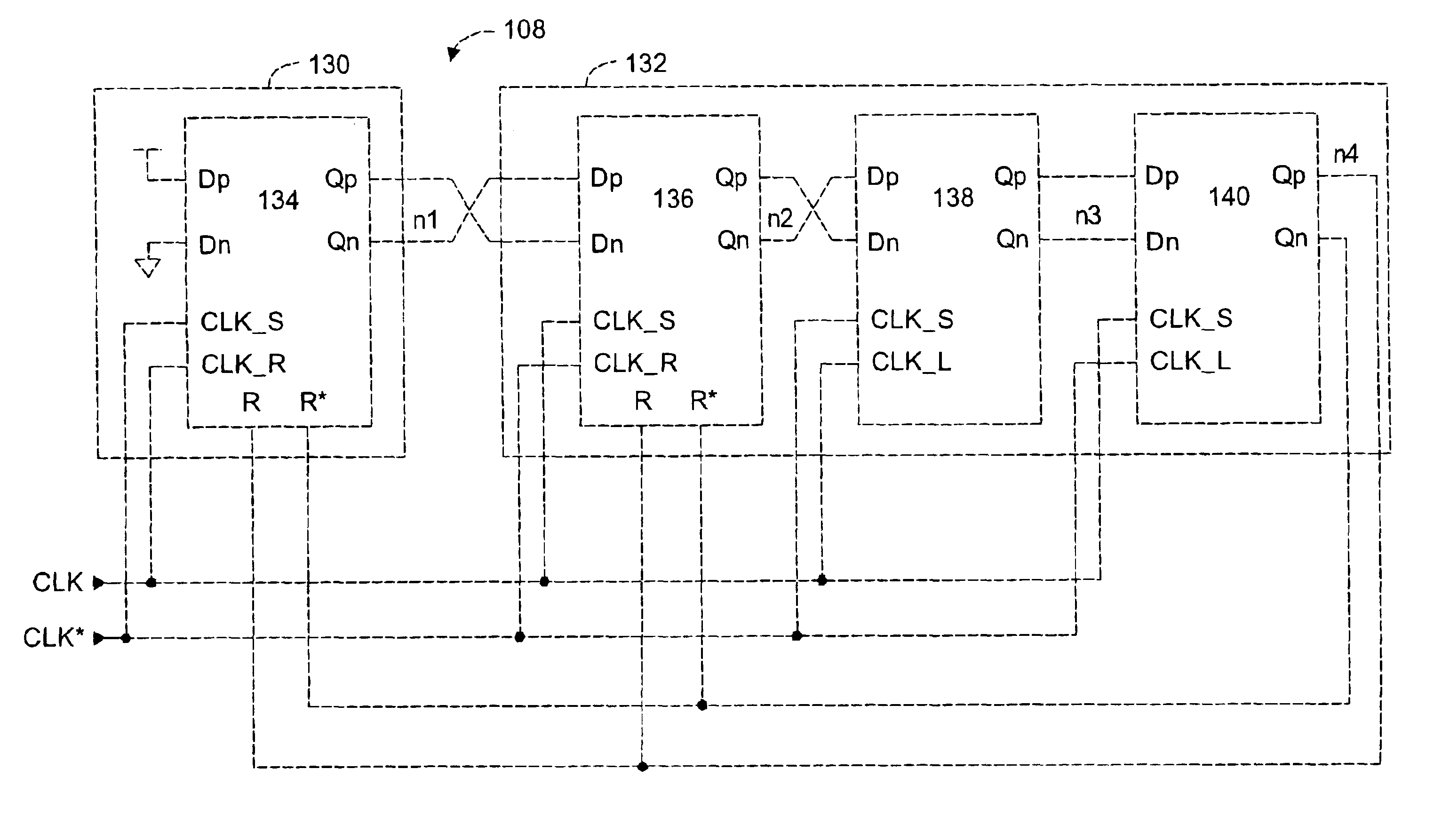
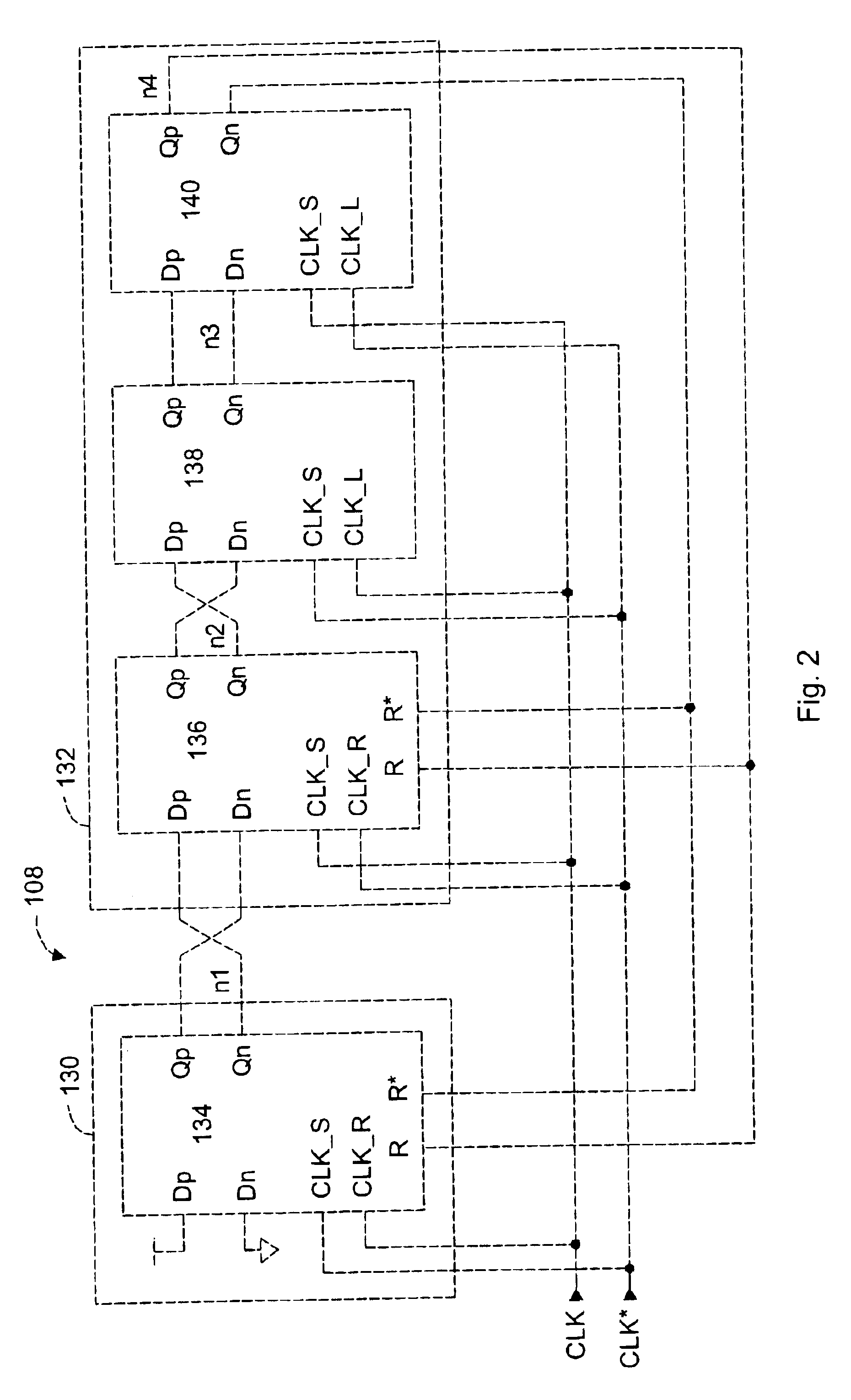
A frequency divider circuit for providing a divided clock signal having a frequency that is a factor less than the frequency of an incoming system clock signal is disclosed. The frequency divider includes a clock generator circuit coupled to a delay circuit that operates in an active and a reset phase to provide a divided clock signal from the system clock signal. In the active phase, the clock generator circuit drives the divided clock signal to a first logic state until a reset signal is received. The delay circuit then generates the reset signal at a number of system clock transitions after the divided clock signal is driven to the first logic state. In the reset phase, the first two flip flops are reset only, the delay formed by the second two flip-flops does not have any reset inputs, however, their inputs are reset to a logic ‘0’ two clock cycles after the reset signal is asserted. The delay circuit therefore maintains a 50% duty cycle for the divided clock signal. More partic...


PUM


Abstract

A frequency divider circuit for providing a divided clock signal having a frequency that is an odd integer factor less than the frequency of an incoming system clock signal. The frequency divider includes a clock generator circuit coupled to a delay circuit which operates in an active and a reset phase to provide a divided clock signal from the system clock signal. In the active phase, the clock generator circuit drives the divided clock signal to a first logic state until a reset signal is received. The delay circuit then generates the reset signal at a predetermined number of system clock edges after the divided clock signal is driven to the first logic state. In the reset phase, both the clock generator circuit and the delay circuit are reset in response to the reset signal such that the clock generator circuit immediately drives the divided clock signal to a second logic state, and the delay circuit disables the reset signal within the predetermined number of system clock edges. The delay circuit maintains a 50% duty cycle for the divided clock signal.

Description

FIELD OF THE INVENTIONThis invention relates generally to frequency division techniques for RF (Radio Frequency) signals. More particularly, the present invention relates to a circuit for converting a system clock signal to a clock signal having a reduced frequency.BACKGROUND OF THE INVENTIONMost electronic devices require a clock signal to synchronize operations of its internal components with each other. This clock signal is commonly referred to as the system clock, and can be provided by a crystal oscillator having a fixed frequency. Telecommunication devices also require clock signals for transmission and reception of RF signals in addition to a system clock.Advances in circuit design and semiconductor manufacturing techniques have increased the maximum operating frequency of high performance electronic devices. For example, current Intel Pentium class microprocessors can run at a system clock frequency between 1 GHz and 2 GHz.Unfortunately, some components of an electronic devi...

Claims


Application Information

Patent Timeline
IPC IPC(8): H03K23/54H03K23/00H03K19/20H03K23/70
CPCH03K23/544
Inventor LEIFSO, CURTIS R.TILLER, SAMUEL A.
Owner BLACKBERRY LTD
Why Eureka
Try Eureka