Coupling mechanism for a two piece printer cartridge

Active Publication Date: 2005-03-22
LEXMARK INT INC
View PDF10 Cites 18 Cited by
  • Summary
  • Abstract
  • Description
  • Claims
  • Application Information

AI Technical Summary

Benefits of technology

Thus by the present invention, a two piece toner cartridge may be removed from an imaging device and handl

Problems solved by technology

Although the biasing mechanism provided by the cover may comprise a spring or springs more costly than springs or other forcing mechanism which might be

Method used


Image

  • Coupling mechanism for a two piece printer cartridge
  • Coupling mechanism for a two piece printer cartridge
  • Coupling mechanism for a two piece printer cartridge

Examples


Example

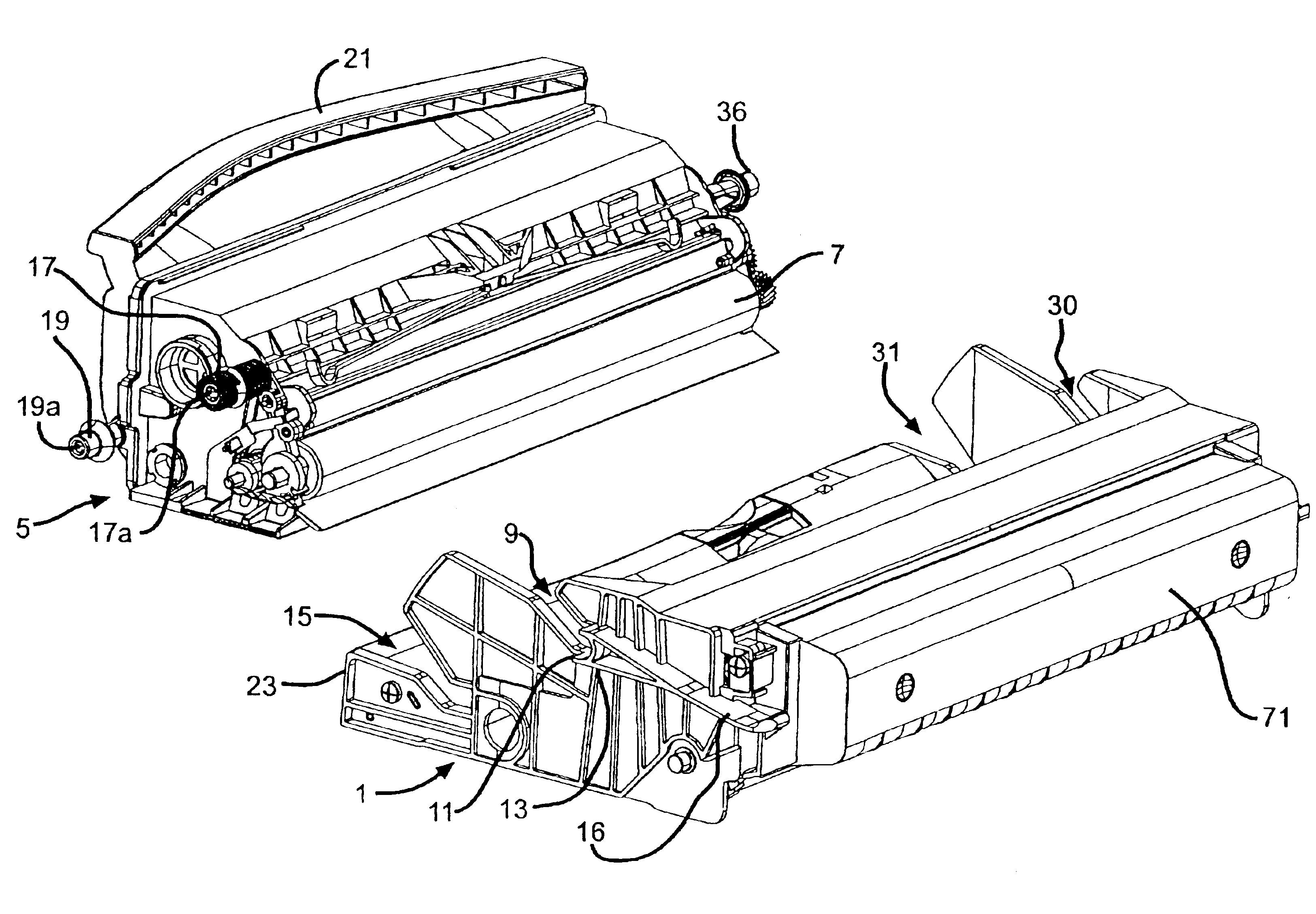
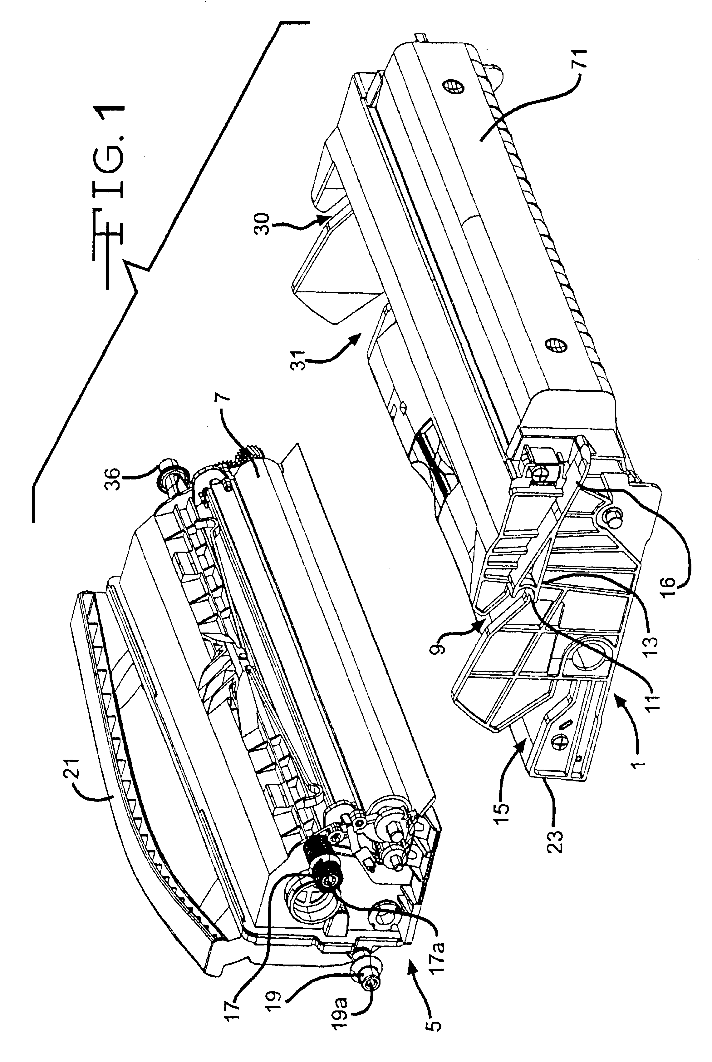
FIG. 1, presents a pictorial view of a two piece cartridge assembly illustrating the developer unit 5 separated from the photoconductor unit 1. Developer unit 5 includes the developer roller 7 and toner (not shown). The right side of photoconductor unit 1 includes an upper guide channel 9 ending in a flat section 11 having a rear wall 13. The right side of photoconductor unit 1 also includes a similar, lower guide channel 15. Planar member 16 is a guide for installation of photoconductor unit 1 within a printer. Similarly the left side of photoconductor unit 1 includes an upper guide channel 30 and a lower guide channel 31.

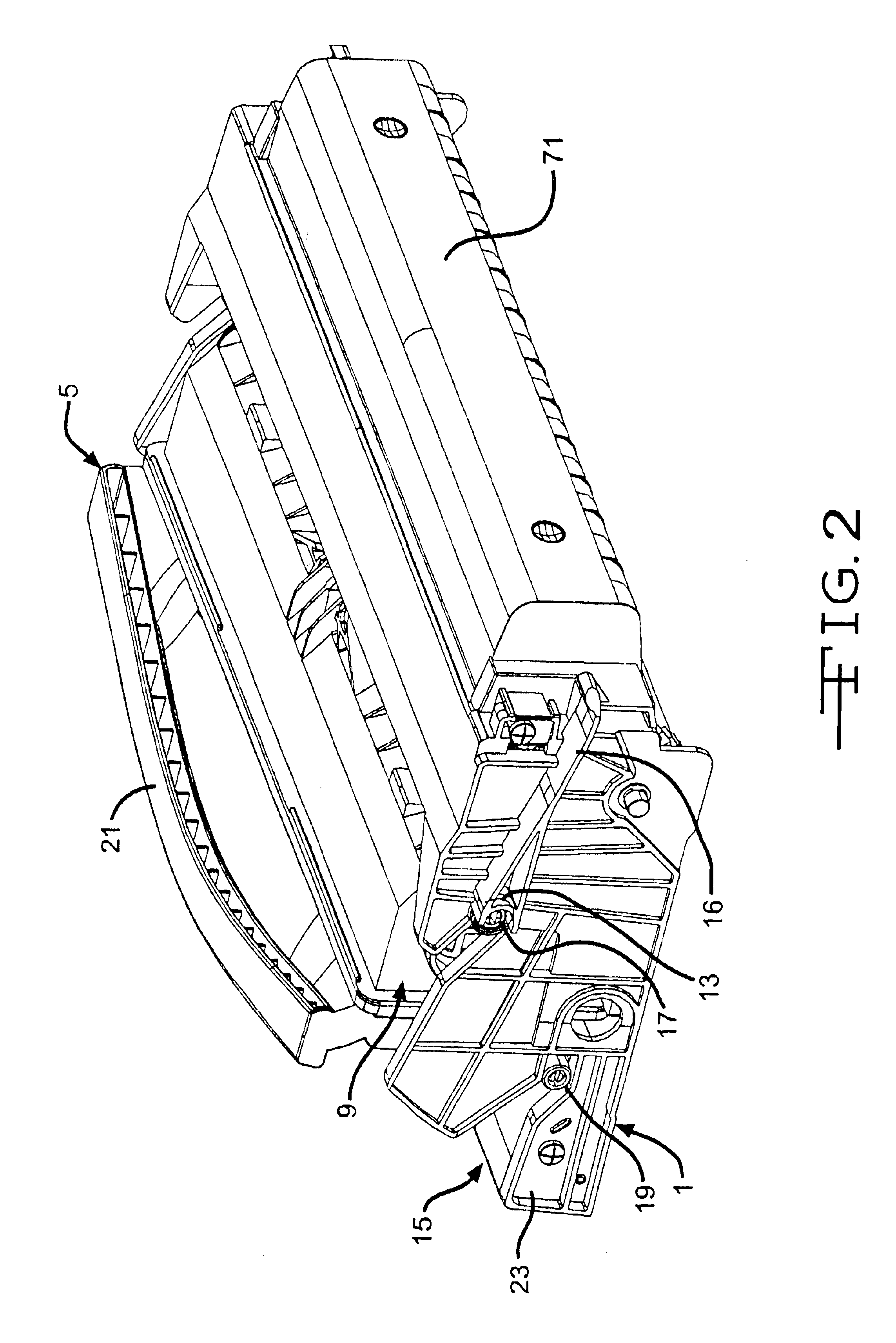
The right side of developer unit 5 includes an upper guide stud 17 and a lower guide stud 19. Similarly the left side of developer unit 5 includes an upper guide stud 36 and a lower guide stud 35 as best illustrated in FIG. 4. FIG. 2 illustrates the photoconductor unit 1 and the developer unit 5 assembled in their normal working configuration. Guide stud 17 fits w...


PUM


Abstract

In a two piece toner cartridge assembly, as typically used in a computer and/or facsimile printing device, comprising separable photoconductor and developer units a unique coupling device is provided whereby the cartridge assembly may be removed from the printing device without the photoconductor unit separating from the developer unit for paper jam clearance or unit replacement. However, if desired the developer unit may be separately removed from the printing device for servicing or replacement without removal of the photoconductor unit.

Description

TECHNICAL FIELDThe present invention generally relates to electrophotographic imaging devices and, more particularly to a two piece printer cartridge assembly having a separately replaceable developer and a photoconductor, which are typically biased together when installed in an imaging device such as a computer printer or facsimile machine. More specifically, the present invention relates to a blocking mechanism whereby the two piece cartridge may be removed as a combined assembly from the imaging device, or the developer unit, having the toner supply therein, may be singly removed for replacement by the user without having to remove the photoconductor.PRIOR ARTHeretofore electrophotographic toner cartridges were of the unitary type typically including a developer section and a photoconductor section connected to one another so that the developer roller, of the developer, is pressed against the photoconductor drum, of the photoconductor, with a predetermined and controlled pressure...

Claims


Application Information

Patent Timeline
IPC IPC(8): G03G21/18
CPCG03G21/1821G03G2221/1853
Inventor BLAINE, DAVID CLAYBUCHANAN, JOHN ANDREWCARTER, PHILIP SCOTKERLEY, MATTHEW THOMASNEWMAN, BENJAMIN KEITHROGERS, MATTHEW LEE
Owner LEXMARK INT INC
Why Eureka
Try Eureka