Film dressing

Active Publication Date: 2011-09-22
NITTO DENKO CORP
View PDF1 Cites 10 Cited by
  • Summary
  • Abstract
  • Description
  • Claims
  • Application Information

AI Technical Summary

Benefits of technology

[0033]In the film dressing according to the present invention (hereinafter also simply referred to as the dressing), the carrier is, firstly, divided by a dividing portion into a carrier first portion and a carrier second portion. Because is this allows the entire dressing to be easily foldable at the dividing portion, it is possible to preferably fix the catheter to the skin even if the catheter is elevated.
[0034]Next, in the present invention, a flap that covers the aforementioned carrier-dividing portion is provided, the flap being divided into two pieces which are joined to a carrier first portion and a carrier second portion, respectively, to yield a holding margin. This allows the two divided carriers to be separated easily by picking the flap, even while wearing rubber gloves for medical use.
[0035]In the present invention, in addition to the above-described improvement in the carrier, a dividing portion

Problems solved by technology

However, when the present inventors extensively investigated the actual status of use of conventional film dressings, the problem shown below was revealed.
The aforementioned problem is a problem with a lack of the ease of carrier separation while wearing rubber gloves because of the absence of an adequate holding margin due to a thin carrier.
However, with the configuration described in the publication, only one of the two divided sections of the carrier is separated by the “support release piece”, whereas the other section of the carrier remains as it is, and is still difficult to separate.
However, that embodiment does not pose a

Method used


Image

  • Film dressing
  • Film dressing
  • Film dressing

Examples


Example

Example 1

(Film Dressing Body)

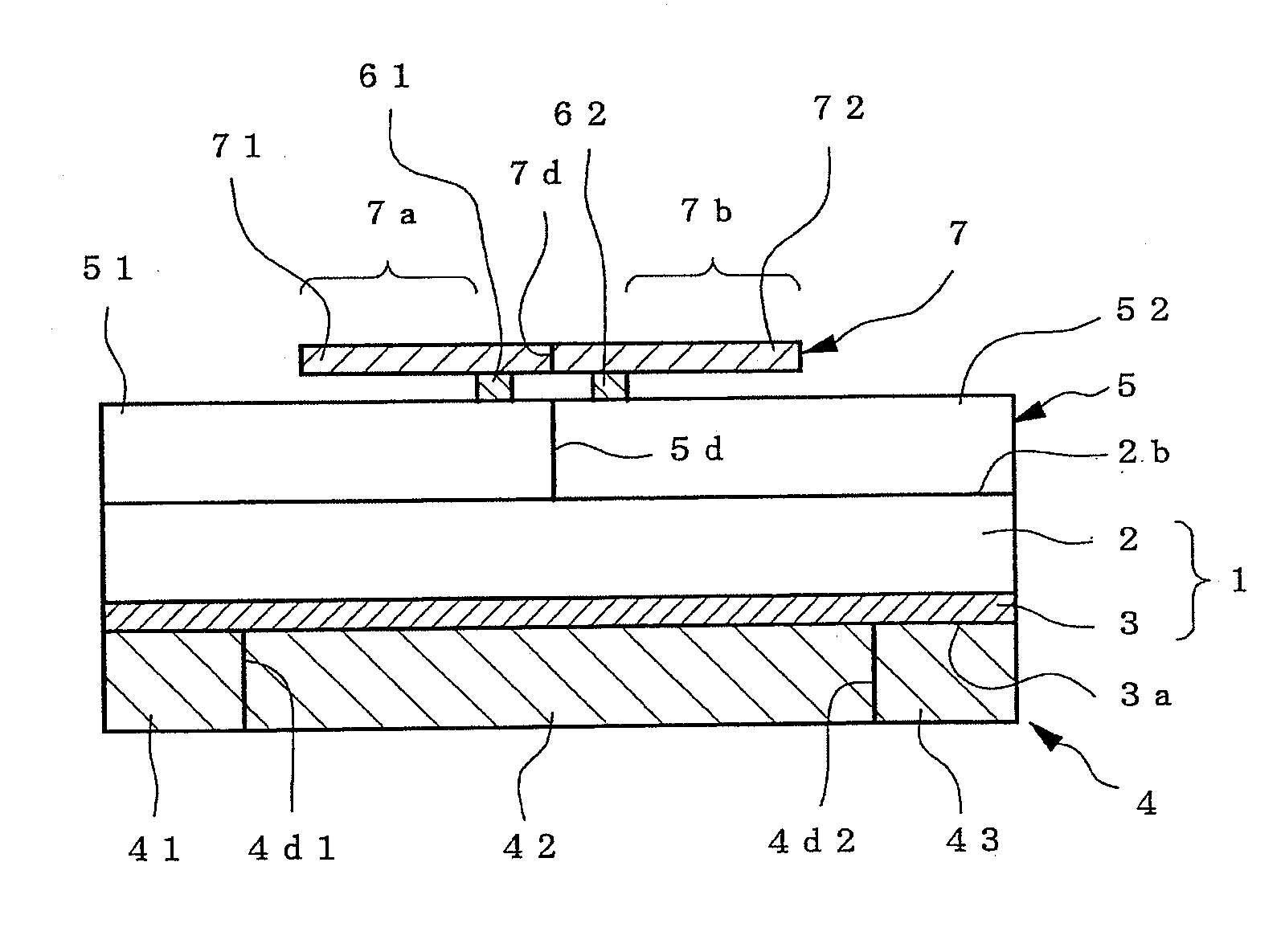
[0142]A adhesive layer consisting of an acrylic-series adhesive was provided on a film 30 μm thick made of polyurethane to obtain a thickness of 30 μm, and this was used as the film dressing body.

(Release liner)

[0143]A release liner consisting of paper 100 thick whose surface has been treated with silicone resin was bonded to the adhesive face of the aforementioned adhesive layer.

(Carrier)

[0144]As a carrier, a film 40 μm thick made of biaxial oriented polypropylene (OPP) was releasably applied onto the back face of the film dressing body by extrusion laminate molding.

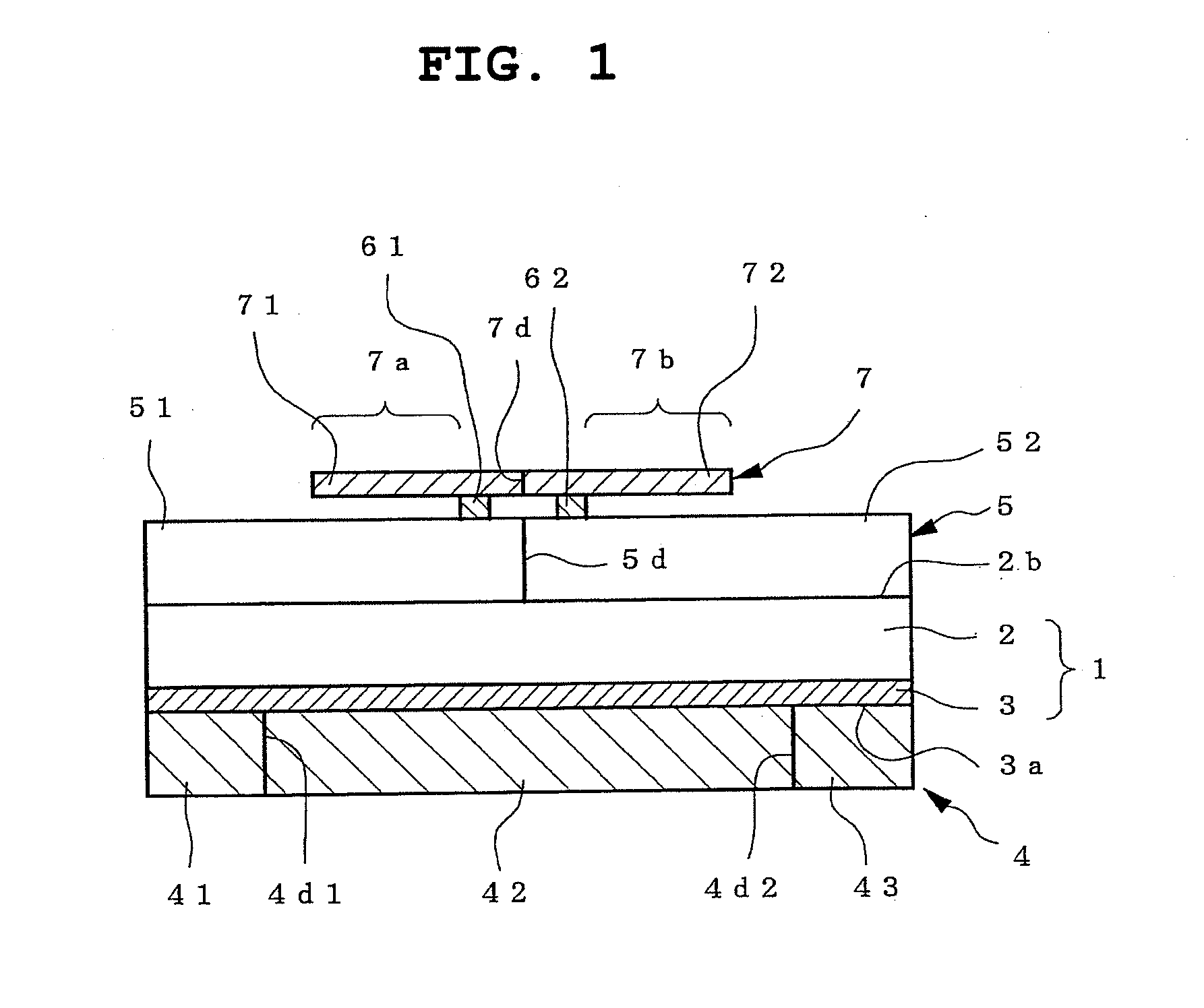
[0145]The central portion of the carrier had a linear notch line added thereto in a way such that the carrier would be completely divided, as shown in FIG. 2(b), and this was used as the carrier-dividing portion. Formation of the carrier-dividing portion was achieved using a die cut roll.

(Flap Layer)

[0146]A flap layer 40 μm thick and 50 mm wide made of an unwoven fabric was laminated coverin...

Example

Example 2

[0154]In this example, a film dressing was prepared in the same manner as the example above except that the flap layer was formed with an OPP film 30 μm thick, and that the distance from the carrier-dividing portion to the bonding portion was set at 4 mm.

[0155]The manipulability and fixability were good as in Example 1 above.

Example

Example 3

[0156]In this example, a film dressing was prepared in the same manner as Example 2 above except that the linear carrier-dividing portion was replaced with a band-shaped carrier-dividing portion, width of 10 mm, extending in a straight line, that the distance from the end of the band-shaped carrier-dividing portion to the bonding portion was set at 4 mm, and that only one release liner-dividing line was present on either side.

[0157]The manipulability and fixability were good as in Example 2 above.


PUM


Abstract

Disclosed is a film dressing comprising a film dressing body. The film dressing body (1) comprises a film (2) and a pressure-sensitive adhesive layer (3) provided on one side of the film (2). The film dressing further comprises a release liner (4) covering the pressure-sensitive adhesive layer (3) on its adhesive face, and a carrier (5) covering the backside of the film (2). A carrier division part (5d) is provided to divide the carrier (5) into a carrier first part (51) and a carrier second part (52). A flap layer (7) is stacked so as to cover the carrier division part (5d). A flap layer division part (7d) is provided in the flap layer (7) to divide the flap layer (7) into a flap layer first part (71) and a flap layer second part (72) which are partially joined respectively on the carrier first pat (51) and the carrier second part (52). Preferably, division parts (4d1, 4d2) are provided in the release liner (4).

Description

TECHNICAL FIELD[0001]The present invention relates to a film dressing for medical use or surgical use. More particularly, the present invention relates to a film dressing to be used, for example, for covering a wounded area, or fixing a medical device such as a catheter.BACKGROUND ART[0002]Being widely used to fix medical devices such as catheters, as a wound-covering material, and for other purposes, the film dressing is a kind of adhesive sheet comprising a film adaptive to the skin and an adhesive layer provided on one primary face of the film.[0003]Any film dressing, while in the state before use (during the distribution stage and the like), normally assumes a multilayer laminated structure comprising the aforementioned adhesive sheet and the following elements (a) and (b) added thereto.[0004](a) A release liner that covers the adhesive layer face (adhesive face).[0005](b) A carrier laminated as a separable support layer on the other primary face (back face) of the film (the car...

Claims


Application Information

Patent Timeline
IPC IPC(8): B32B33/00
CPCA61F13/023A61F2013/00412A61F2013/00812A61F2013/00817A61F2013/00868Y10T428/14Y10T428/1471Y10T428/1476Y10T428/24215Y10T428/15Y10T428/2419B32B7/06
Inventor FUNAKOSHI, YOSHIOSUZUKI, SEISHI
Owner NITTO DENKO CORP
Why Eureka
Try Eureka