Ice dispensing chute

Active Publication Date: 2005-01-13
MARMON FOODSERVICE TECH INC
View PDF5 Cites 9 Cited by
  • Summary
  • Abstract
  • Description
  • Claims
  • Application Information

AI Technical Summary

Benefits of technology

[0004] In accordance with the present invention, there is provided an improved ice dispensing chute assembly which includes an ice chute that is secured to an ice retaining bin and has an actuation lever pivotally secured thereto. A crank and slider linkage mechanism is operated by the actuation lever for opening an ice gate. The linkage mechanism efficiently and directly translates a pivotal rotary motion of the actuation lever into a linear motion for lifting the ice gate. The ice chute has a top half and a bottom half that can easily be separated for cleaning purposes and the chute is provided with a sloped ice launch ramp over which ice discharged from the ice bin flows and that allows the ice to fall through the chute in a generally uniform trajectory over a predict

Problems solved by technology

It is known to operate or power the ice gate between open and closed positions with a solenoid, but that approach adds undesirable cost to the ice dispenser.
Purely manually operated ice gate mechanisms are also known, but such gates are subject to issues such as mechanical complexity, difficulty of disassembly

Method used


Image

  • Ice dispensing chute
  • Ice dispensing chute
  • Ice dispensing chute

Examples


Example

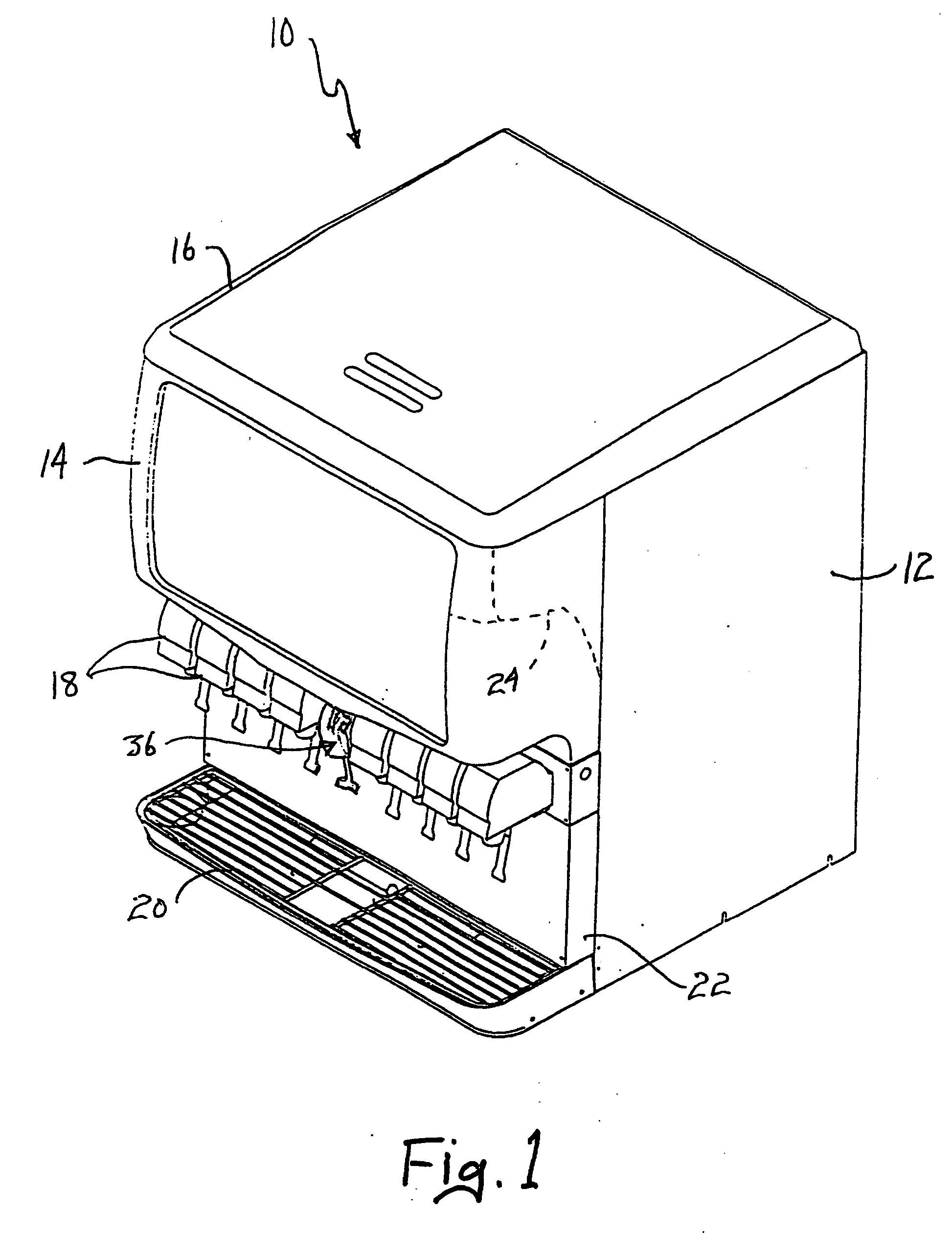
[0011] An ice dispensing chute assembly according to the teachings of the present invention is advantageous for use in a combined beverage and ice dispensing machine of a type shown in FIG. 1 and indicated generally at 10. As is conventional, the dispenser 10 includes an outer housing 12, a merchandising cover 14 and a removable ice bin filling cover 16. A plurality of beverage dispensing valves 18 is secured to a front surface of the dispenser above a drip tray 20 and adjacent a splash panel 22, and internally of the dispenser is an ice retaining bin 24.

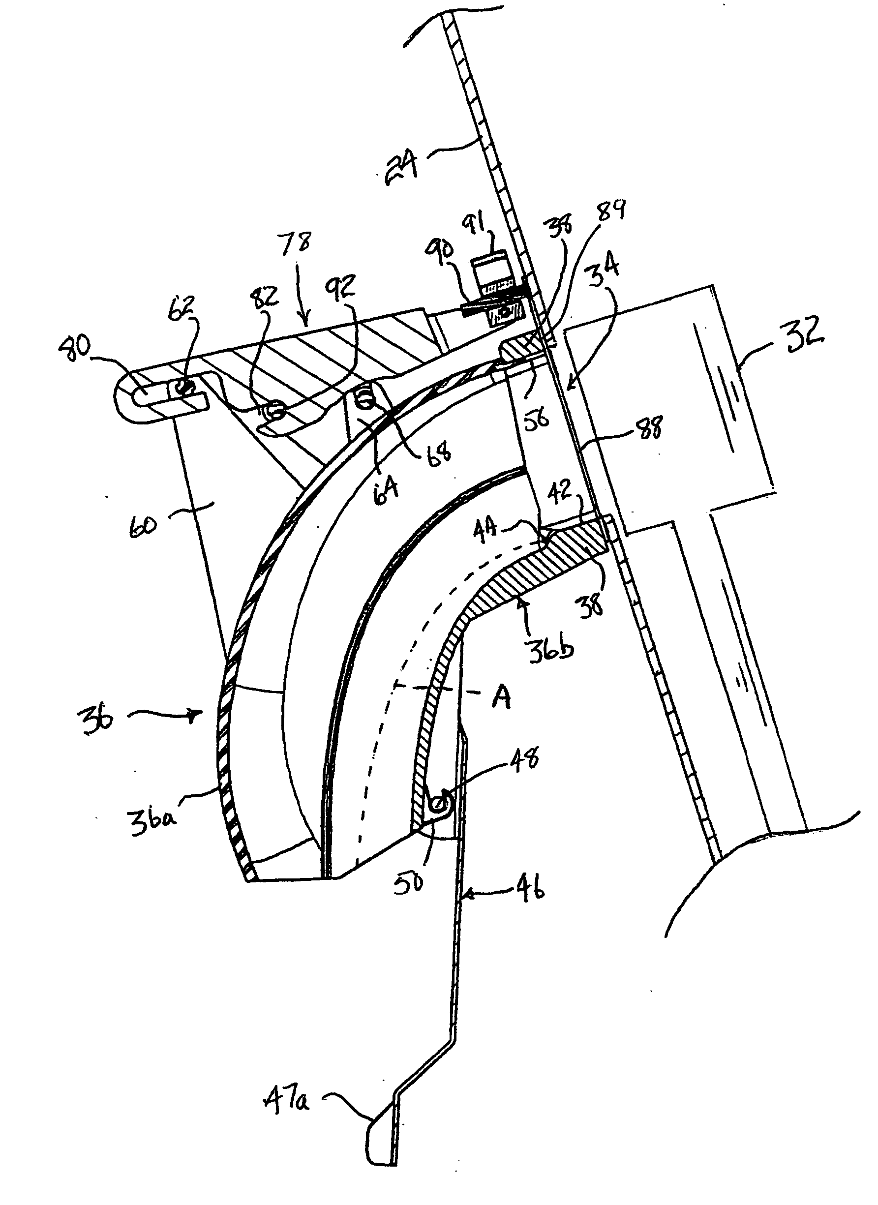
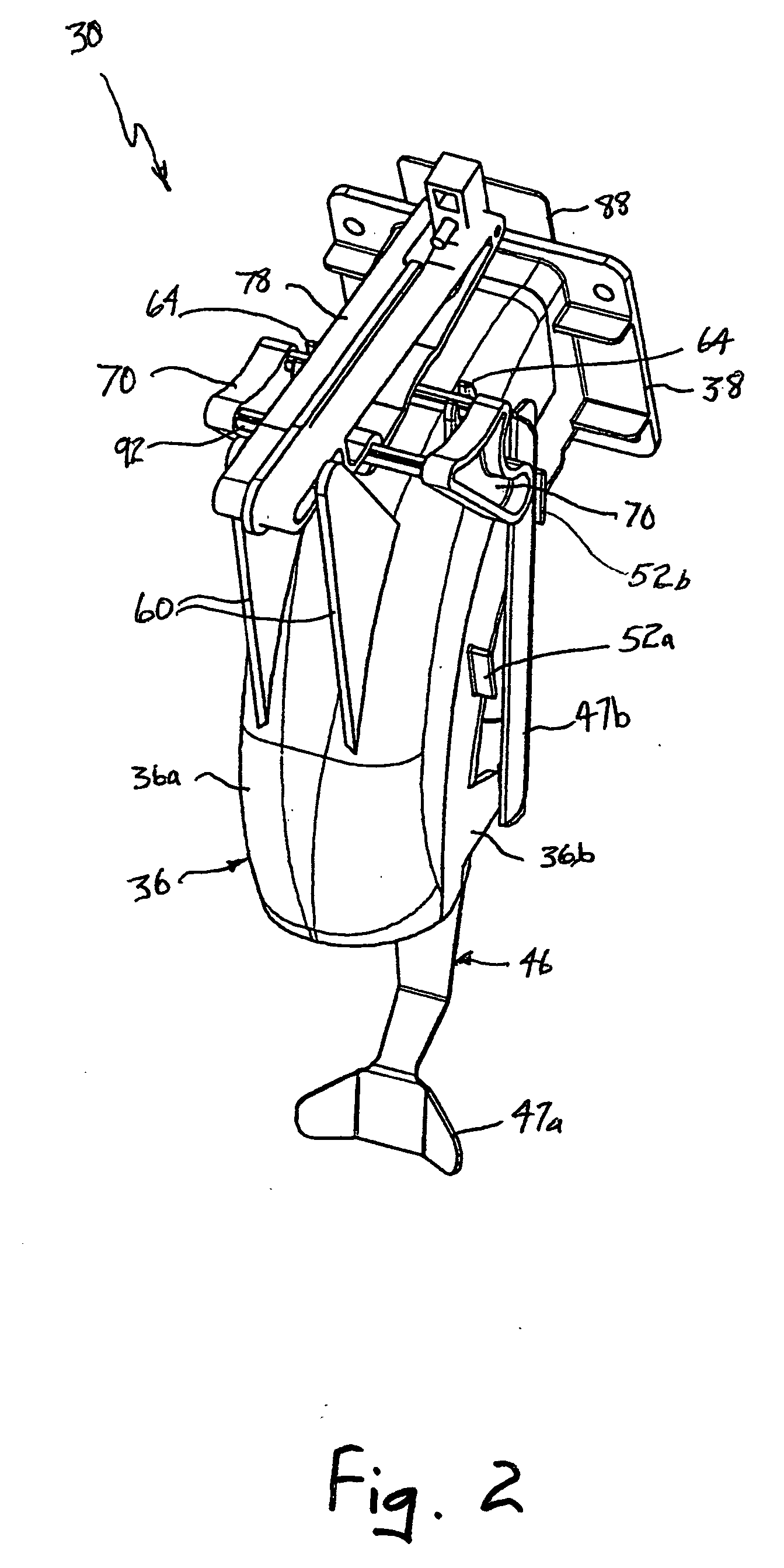
[0012] As seen in FIGS. 2 and 3, an ice dispensing chute assembly embodying the teachings of the invention is indicated generally at 30 and mounted to an upper front portion of the ice bin 24. A conventional rotary ice lifting mechanism is in the ice bin 24 and includes ice lifting arm ends 32 (one of which is shown) that move ice particles from a lower level in the ice bin up to an elevated ice dispense outlet opening 34 from the ...


PUM

PropertyMeasurementUnit
Lengthaaaaaaaaaa
Gravityaaaaaaaaaa
Trajectoryaaaaaaaaaa

Abstract

An ice dispensing chute mechanism is characterized by an ice chute adapted for attachment at an upper ice inlet end to an ice retaining bin at an ice outlet from the bin. An actuating arm is pivotally mounted on the ice chute and has a lower end for being contacted and moved by a receptacle into which ice is to be dispensed from a lower ice discharge end of the chute and an upper end for contacting and moving a linkage mechanism upon rotation of the actuating arm by the receptacle. The linkage mechanism is pivotally mounted on the ice chute and is coupled to an ice gate that is linearly moved by the linkage mechanism between open and closed positions that establish and interrupt communication between the upper inlet to the chute and the ice outlet opening from the bin. Movement of the linkage mechanism by the actuating arm operates the linkage mechanism to translate the rotational movement of the actuating arm into linear movement of the ice gate between its open and closed positions to dispense ice and to cease dispensing ice into the receptacle. The ice chute consists of two halves that snap together in a releasable manner to permit easy disassembly of the ice chute for cleaning, repair or replacement of parts. The upper inlet to the ice chute is configured to impart to ice particles a trajectory through the chute that guides the ice particles into the receptacle while preventing the vast majority of the ice particles from contacting interior surfaces of the chute.

Description

[0001] This application claims benefit of provisional application Ser. No. 06 / 463,771, filed Apr. 17, 2003.BACKGROUND OF THE INVENTION [0002] The present invention relates generally to ice dispensing equipment and in particular to ice dispensing equipment for dispensing ice into a cup. [0003] Ice dispensing equipment is well known and generally employs an ice retaining bin and an ice chute connected thereto. Ice is dispensed from the bin through the chute and into a suitable receptacle. Dispensing of ice is typically initiated by actuation of a switch which operates an electrically driven dispensing mechanism. Particularly in equipment which combines the dispensing of ice and beverages, the ice dispensing mechanism consists of an agitator that agitates ice retained in the bin to prevent congealing and agglomeration of the discrete particles of ice into a mass of ice and to keep the discrete particles in free flowing form and that, during an ice dispensing operation, moves and lifts ...

Claims


Application Information

Patent Timeline
IPC IPC(8): F25C5/00
CPCF25C5/007F25C5/24
Inventor JABLONSKI, THADDEUS M.SCHEURICH, MICHAEL J.
Owner MARMON FOODSERVICE TECH INC
Why Eureka
Try Eureka