

Machine tool and control device of the machine tool
- Summary
- Abstract
- Description
- Claims
- Application Information
AI Technical Summary
Benefits of technology
Problems solved by technology
Method used
Image

Examples
first embodiment
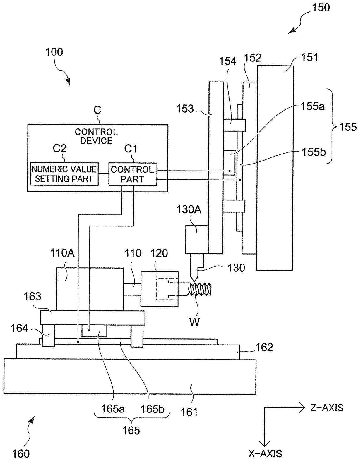
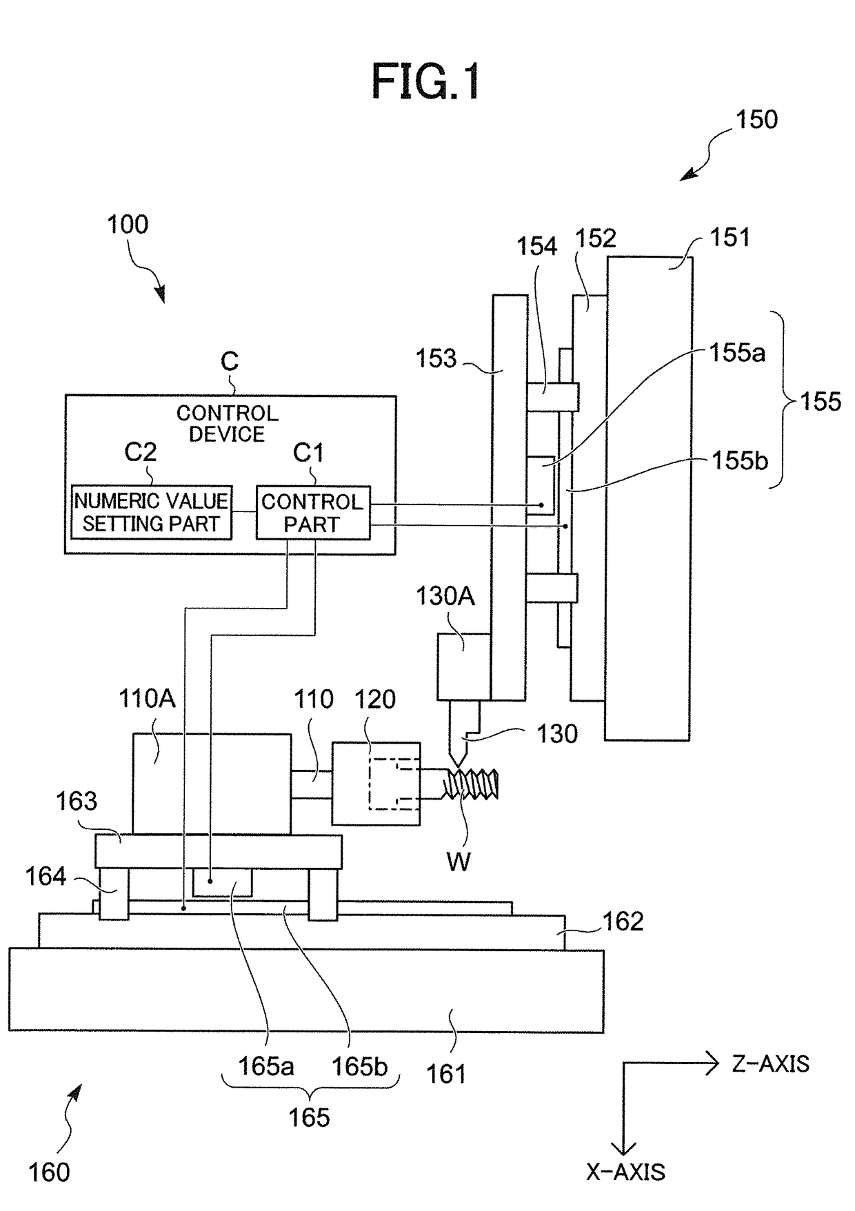
[0023]FIG. 1 is a diagram illustrating a machine tool 100 having a control device C as the present invention. The machine tool 100 includes a spindle 110 and a cutting tool rest 130A. The spindle 110 has a chuck 120 provided at a tip thereof. A workpiece W is held by the spindle 110 via the chuck 120, and the spindle 110 is configured as a workpiece holding unit to hold a workpiece. The spindle 110 is supported by a spindle stock 110A so as to be rotatably driven by a spindle motor that is not illustrated. A conventional built-in motor or the like formed between the spindle stock 110A and the spindle 110 may be used as the spindle motor in the spindle stock 110A.
[0024]The spindle stock 110A is mounted on a bed side of the machine tool 100 so as to be movable in a Z-axis direction, which is an axis direction of the spindle 110, by a Z-axis direction feeding mechanism 160. The spindle 110 moves in the Z-axis direction by the Z-axis direction feeding mechanism 160 via the spindle stock...
second embodiment
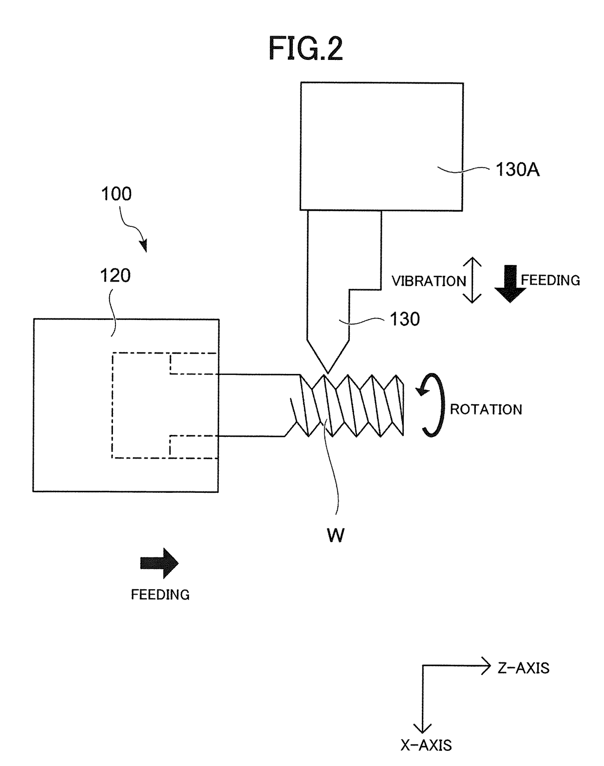
[0063]According to the machine tool 100 and the control apparatus C of the machine tool 100 as the present invention obtained as described above, the frequency of the reciprocal vibration of the n+1th cutting work is higher than the frequency of the reciprocal vibration of the nth cutting work, and the control part C1 makes the path traced by the cutting tool 130 in the backward movement of the n+1th cutting work reach the path traced by the cutting tool 130 in the nth cutting work as the forward movement switches to the backward movement once in multiple vibrations of the n+1th cutting work. Thus, it is possible to perform a threading work while efficiently separating a chip and also to gradually flatten a bottom surface of a thread as the number of cutting works increases.
PUM
| Property | Measurement | Unit |
|---|---|---|
| Phase | aaaaa | aaaaa |
| Frequency | aaaaa | aaaaa |
Abstract
Description
Claims
Application Information