Wide range multi-phase delay-locked loop

a delay-locked loop and wide-range technology, applied in the field of data communication, can solve the problems of detectors raising several design problems, phase adjustment circuitry tending to oscillate, and misplaced sampling clocks

Inactive Publication Date: 2005-04-05
SUPER INTERCONNECT TECH
View PDF6 Cites 41 Cited by
  • Summary
  • Abstract
  • Description
  • Claims
  • Application Information

AI Technical Summary

Problems solved by technology

Furthermore, if a Delay-Locked Loop (DLL) is used in a transmitter, special consideration must be made in designing a wide-range multi-phase DLL due to a so-called stuck problem.
Thus, the phase adjustment circuitry tends to oscillate when it is in a locked steady state.
This misplacement of the sampling clock is due to the asymmetric nature of severe jitter as illustrated by the histogram in FIG. 1B, and is not desirable.
Also, a conventional tracked three-times (3×) oversampling phase detector raises several design problems due to long pumping pulses persisting for one Voltage Controlled Oscillator (VCO) cycle time.
Conventional Voltage Controlled Oscillators (VCOs) that use replica bias circuits are known to produce most of their jitter due to the noise in the bias voltage from the replica circuit.

Method used


Image

  • Wide range multi-phase delay-locked loop
  • Wide range multi-phase delay-locked loop
  • Wide range multi-phase delay-locked loop

Examples


Embodiment Construction

A method and apparatus for implementing an oversampling transceiver with dead-zone phase detection is disclosed. In the following description, for purposes of explanation, specific nomenclature is set forth to provide a thorough understanding of the present invention. However, it will be apparent to one skilled in the art that these specific details are not required in order to practice the present invention. For example, certain teachings of the present invention have been described with reference to a phase-locked loop circuit in a data communication transceiver device. However, the signal phase comparison and locking techniques of the present invention can easily be applied to other types of phase-locked loop applications or in other applications that require a phase comparison.

Transceiver Architecture Overview

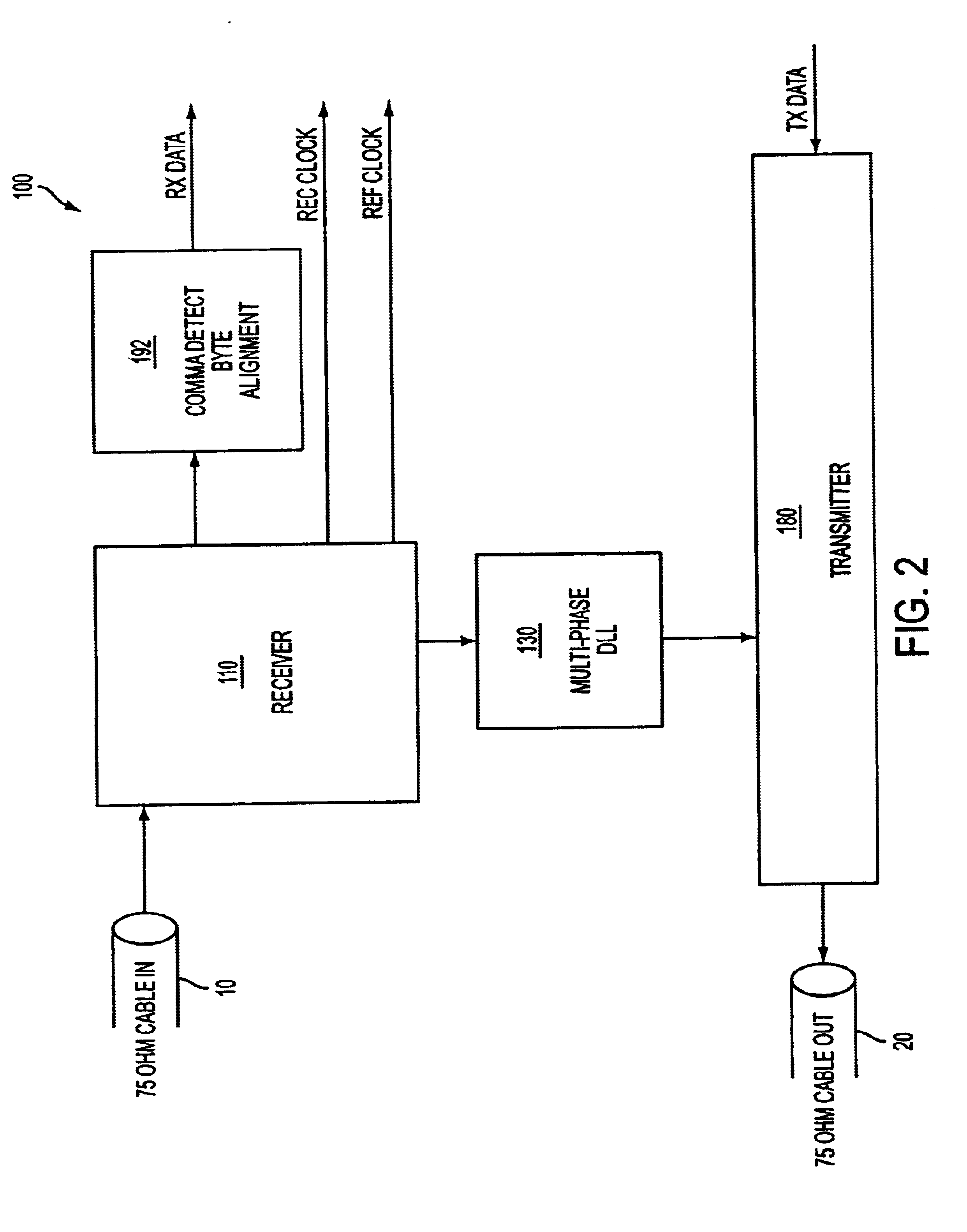
FIG. 2 illustrates a simplified block diagram of a serial link transceiver 100, in accordance with the present invention. Included is a 75 ohm cable-in 10, a receiver 100, ...


PUM


Abstract

A delay locked loop apparatus includes a first delay element to receive a reference signal, to delay the reference signal by a delay time, and to output a first delayed signal. A second delay element is used to receive the first delayed signal, to delay the first signal delayed signal by the delay time, and to output a second delayed signal. Also included is a harmonic lock prevention circuit to receive the reference signal, the first delayed signal, and the second delayed signal, and to adjust the delay time so that a period of each delayed signal is within a predetermined range.

Description

FIELD OF THE INVENTIONThe present invention relates to the field of data communications. In particular the present invention discloses methods and circuits for robust data recovery on a high-speed serial data link.BACKGROUND OF THE INVENTIONAs serial links are required to operate at higher frequencies and over longer distances, more sophisticated mechanisms have been adopted to recover data from more severely degraded signals. However, conventional serial transceiver systems have shortcomings. For example, a conventional transmitter uses a conventional current mode-driver whose speed is limited to 0.43 / RC due to a passive pull-up resistor. Furthermore, if a Delay-Locked Loop (DLL) is used in a transmitter, special consideration must be made in designing a wide-range multi-phase DLL due to a so-called stuck problem.In a conventional receiver system that uses using oversampling, the receiver Phase-Locked Loop (PLL) is locked to a reference clock rather than to the transmitted signal. ...

Claims


Application Information

Patent Timeline
Patent Type & Authority Patents(United States)
IPC IPC(8): H03L7/113H03L7/091H03L7/14H03L7/08H04L7/033H04L7/04
CPCH03L7/091H03L7/113H04L7/033H03L7/14Y10S331/02H04L7/04
Inventor MOON, YONGSAMAHN, GIJUNGJEONG, DEOG-KYOON
Owner SUPER INTERCONNECT TECH
Why Eureka
Try Eureka