

Laparoscopic illumination apparatus and method
- Summary
- Abstract
- Description
- Claims
- Application Information
AI Technical Summary
Benefits of technology
Problems solved by technology
Method used
Image

Examples
Embodiment Construction
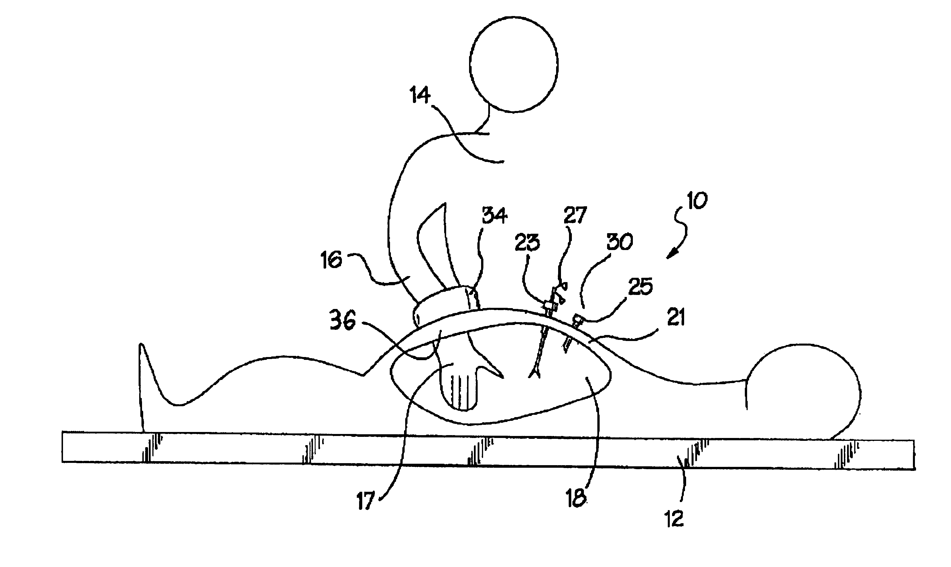
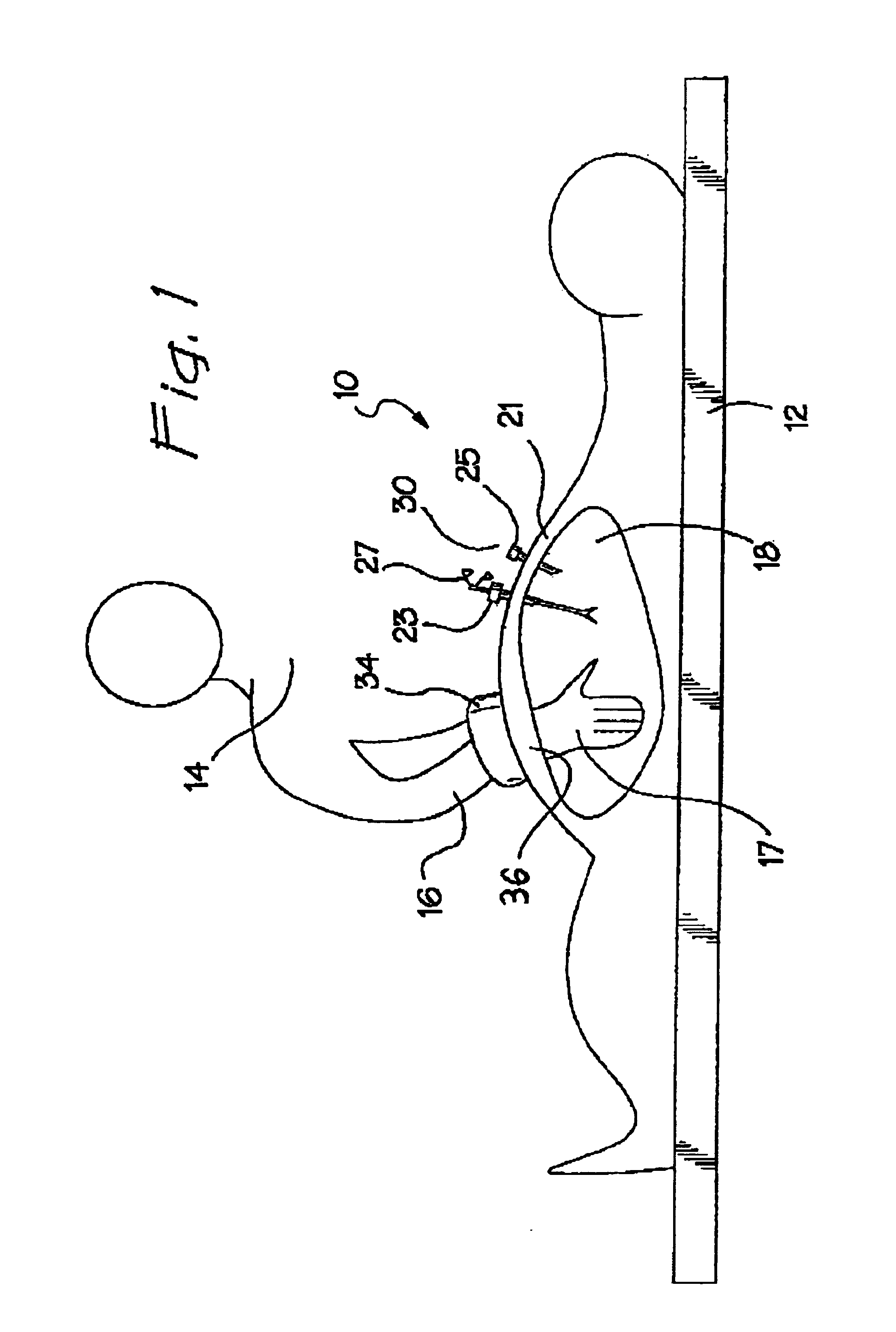
[0061]A patient is illustrated in FIG. 1 and designated generally by the reference numeral 10. The patient 10 is shown in a prone position on an operating table 12, where abdominal surgery is being performed by a surgeon 14 having an arm 16 and a hand 17. In the illustrated example, the operative procedure is performed within an abdominal cavity 18 with instrument access provided through an abdominal wall 21. In this type of operation, commonly referred to as laparoscopic surgery, trocars 23 and 25 are commonly used to provide minimally invasive access through the abdominal wall 21 for instruments such as a grasper 27 and an endoscope 30
[0062]Although the specific focus of this disclosure will be on a preferred laparoscopic procedure, it will be noted that laparoscopic surgery is merely representative of a type of operation wherein a procedure can be performed in a body cavity with minimal access through a body wall.
[0063]Notwithstanding the foregoing generality, it is important to ...
PUM
 Abstract
Description
Claims
Application Information