Chlorine generator

a chlorine generator and generator technology, applied in the field of electrolysis cell improvement, to achieve the effect of simple installation and maintenance, and economic construction

Inactive Publication Date: 2005-09-13
LEMKE CHRIS ALAN
View PDF25 Cites 14 Cited by
  • Summary
  • Abstract
  • Description
  • Claims
  • Application Information

AI Technical Summary

Benefits of technology

[0012]The present invention eliminates the various complicated means described in the earlier patents of apparatus construction. The present invention also allows the use of any direct current power supply

Problems solved by technology

The necessity of the cell to isolate the chlor-alkali process from the environment is obvious

Method used


Image

  • Chlorine generator
  • Chlorine generator
  • Chlorine generator

Examples


Embodiment Construction

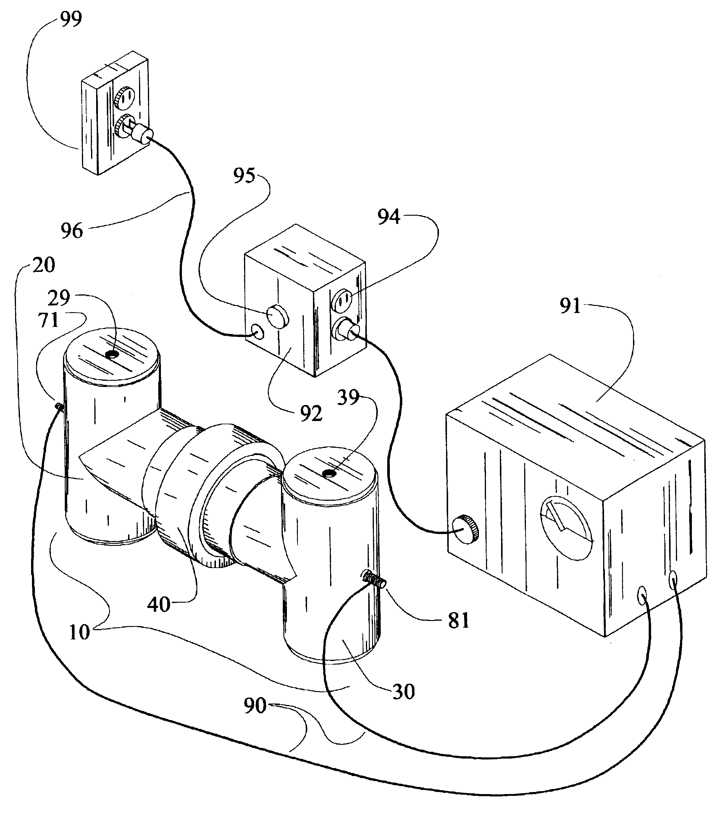
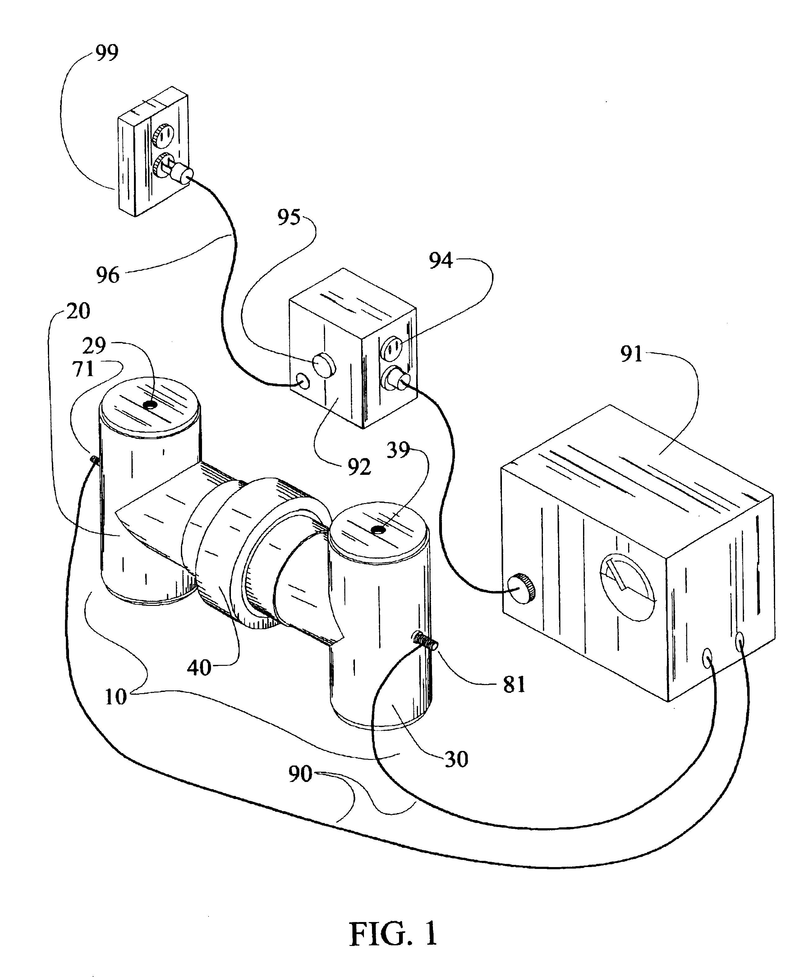
[0027]The configuration of the invention can partake several forms. It is the intention of this narrative to describe in detail the invention for a chlor-alkali system that produces 0.01-1.0 kilograms (0.02-2.2 pounds) of chlorine gas per day. Illustrations of this type of system are shown in FIGS. 1, 2, and 3.

[0028]FIG. 1 is an isometric representation of the invention in its assembled form. As shown in FIG. 1, the invention is comprised of a cell 10 divided into an anode compartment 20 and a cathode compartment 30. Continuity or attachment of anode compartment 20 with cathode compartment 30 is provided by a cell compression collar 40.

[0029]Cell 10 is made of a rigid, non-electrically conductive material such as fiberglass, polyvinyl chloride (PVC) plastic, chlorinated polyvinyl chloride (CPVC) plastic, polyvinylidene fluoride (PVDF) plastic, polytetrafluoroethylene (PTFE) plastic or other plastics that are chemically resistant to the solutions and gases contained within cell 10. M...


PUM

PropertyMeasurementUnit
Electrical conductivityaaaaaaaaaa
Sizeaaaaaaaaaa
Energyaaaaaaaaaa

Abstract

A chlorine generator cell (10) contains components that require physical isolation between the anode compartment (20), cathode compartment (30), and outside environment. The cell (10) also contains a membrane (50) that provides selective electrical conductivity between the anode compartment (20) and cathode compartment (30). The cell (10) consists of a series of pipe fittings that allow access to the interior of cell (10) for placement of water and salt to generate chlorine. The anode stem (71) and cathode stem (81) located outside of cell (10) are connected to a power supply (91). Power supply (91) may be further connected to a power controller (92) that allows for adjustment of the energy output of power supply (91) to the optimum energy level, thus the desired chlorine output. This invention provides a chlorine generator that is portable, yet is allows for expanded size with additional pipe fittings as needed. Furthermore, this invention allows multiple to infinite chlorine output levels with a single cell (10).

Description


Claims


Application Information

Patent Timeline
IPC IPC(8): C02F1/467C02F1/461C25B9/06C25B9/08C25B9/19
CPCC02F1/46104C02F1/4674C25B9/08C02F2201/46115C02F2201/46125C25B9/19
Inventor LEMKE, CHRIS ALAN
Owner LEMKE CHRIS ALAN
Why Eureka
Try Eureka