Sheet stacking apparatus

Inactive Publication Date: 2005-11-08
CANON KK
View PDF10 Cites 24 Cited by
  • Summary
  • Abstract
  • Description
  • Claims
  • Application Information

AI Technical Summary

Benefits of technology

[0014]It is an object of the present invention to provide a sheet stacking apparatus which is capable of reliably sandwiching or catchi

Problems solved by technology

However, if the sheet processing apparatus is configured such that the stack tray is disposed at a location below an original reader and at an upper location inside the main body of the image forming apparatus, and with an angle of inclination smaller than that in the conventional configuration so as to secure a sufficient stacking capacity of the stack tray, the following problem arises.
Therefore, it is difficult to obtain a sufficient stacking capacity of the stack tray when it is disposed at a location below the original reader and at an upper location inside the main body of the image forming apparatus.
Consequently, the sheet cannot be properly sandwiched or caught between the upper and lower sheet discharging rollers by the upper sheet discharging roller being lowered toward the lower sheet discharging roller.
On the other hand, if the discharging speed of the sheet is too low, the sheet discharging rollers which are relatively weak in driving force ca

Method used


Image

  • Sheet stacking apparatus
  • Sheet stacking apparatus
  • Sheet stacking apparatus

Examples


Embodiment Construction

[0053]The present invention will now be described in detail with reference to the accompanying drawings showing a preferred embodiment thereof.

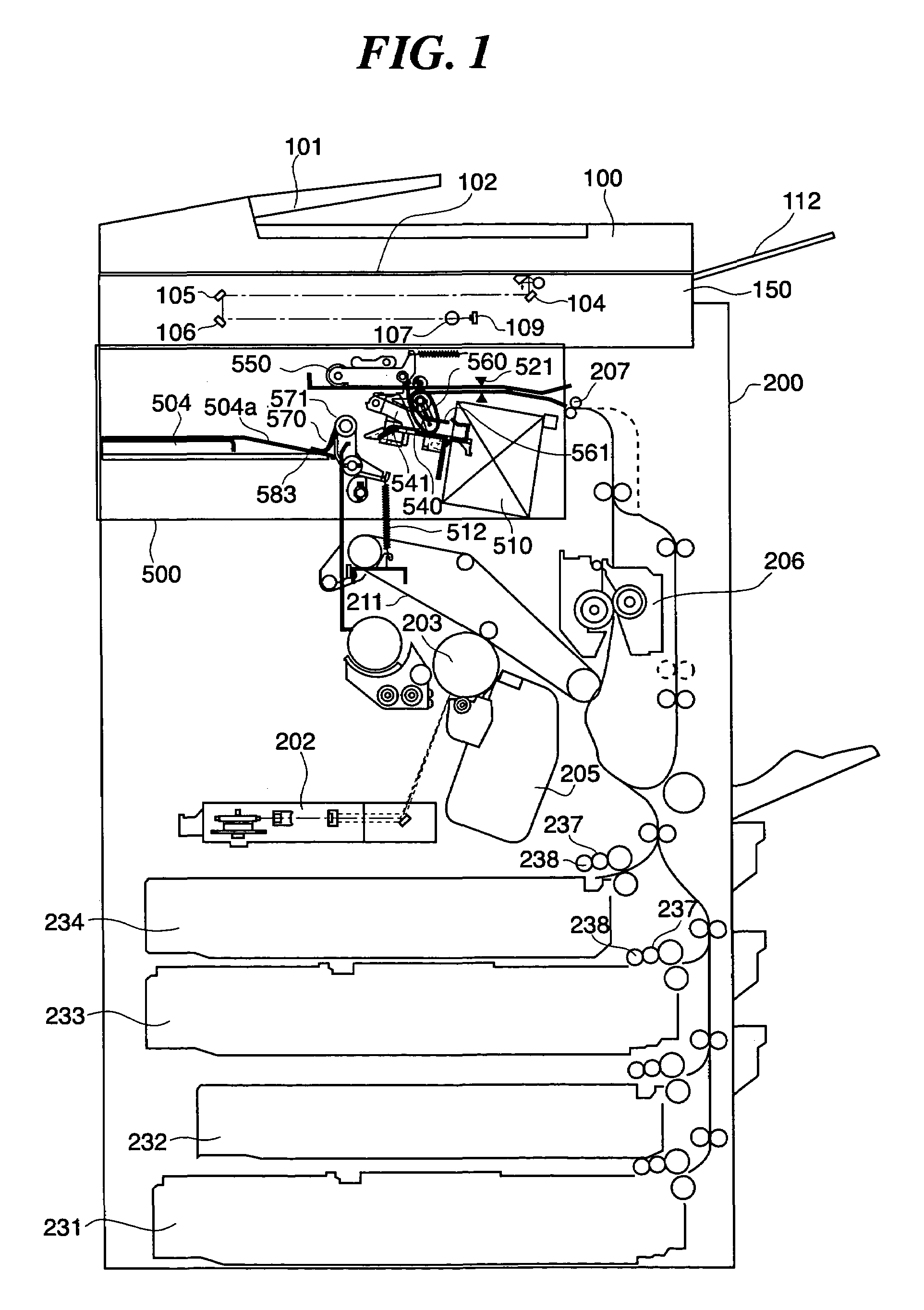
[0054]FIG. 1 is a sectional view showing the construction of an image forming apparatus provided with a sheet stacking apparatus according to an embodiment of the present invention. In the present embodiment, a sheet processing apparatus is provided in the image forming apparatus. In FIG. 1, reference numeral 200 denotes an image forming apparatus main body. An original reader 150 is provided on an upper side of the image forming apparatus main body 200, and an automatic original reader 100 is mounted on top of the original reader 150. Further, the sheet processing apparatus 500 as the sheet stacking apparatus according to the present embodiment, which is stored in a housing of the image forming apparatus, is provided in an upper part of the image forming apparatus main body 200 and below the original reader 150.

[0055]The automatic original r...


PUM

PropertyMeasurementUnit
Thicknessaaaaaaaaaa

Abstract

A sheet stacking apparatus which is capable of reliably sandwiching or catching sheets, and also capable of providing control so as to ensure reliable conveyance of succeeding sheets during the catching operation. A stack tray is provided downstream of a processing tray that stacks sheets. A position on the stacking surface of the stack tray at which the leading end of a sheet having its trailing end passing a discharging section, which discharges sheets toward the processing tray, contacts the stacking surface is lower in level than the highest portion of the processing tray. A swinging arm that discharges the sheets stacked on the processing tray to the stack tray is capable of selectively assuming a catching state in which a sheet discharged to the processing tray is caught by the swinging arm, and a non-catching state in which a sheet discharged to the processing tray is not caught by the swinging arm. The swinging arm is controlled to assume the non-catching state when the discharging section starts discharging a sheet, and switch to the catching state before the trailing end of the sheet discharged by the discharging section passes the swinging arm.

Description

BACKGROUND OF THE INVENTION[0001]1. Field of the Invention[0002]The present invention relates to a sheet stacking apparatus that stacks sheets which have been conveyed.[0003]2. Description of the Related Art[0004]Conventionally, an image forming apparatus which has a sheet processing apparatus incorporated in a housing thereof has been proposed (Japanese Patent Application No. 2001-313041). An image forming apparatus of this type in which sheets are discharged inside the housing enables a large reduction in the space occupied by the sheet processing apparatus. FIG. 29 is a sectional view showing the construction of the conventional image forming apparatus of the type in which sheets are discharged inside the housing. In this image forming apparatus, a processing tray 1001 is mounted in an inclined fashion inside a sheet processing apparatus 1000. Sheets S on which images have been formed inside the main body of the image forming apparatus are temporarily stacked on the processing tr...

Claims


Application Information

Patent Timeline
IPC IPC(8): B65H29/00B65H29/14B65H31/30B65H33/08B65H33/00
CPCB65H29/14B65H31/3027B65H33/08B65H2301/16B65H2301/163B65H2511/414B65H2801/27B65H2220/01B65H2301/4213
Inventor MATSUMOTO, YUZOTSUJINO, HIROMICHIMURATA, MITSUSHIGEHANADA, TAKAKO
Owner CANON KK
Why Eureka
Try Eureka