Display and display drive circuit or display drive method

a technology of display drive and drive circuit, which is applied in the direction of electric digital data processing, instruments, computing, etc., can solve the problems of increasing the size of the connector, the disadvantage of the driving circuit mentioned above, and the increase of the number of input signal interfaces for lighting control

Inactive Publication Date: 2006-03-21
NICHIA CORP
View PDF15 Cites 20 Cited by
  • Summary
  • Abstract
  • Description
  • Claims
  • Application Information

AI Technical Summary

Benefits of technology

[0228]The display apparatus of the invention has a feature to reduce a number of signal lines of the circuit driving the display section disposing a plurality of the lighting devices, and to simplify wiring for low-cost and downsizing. Accordingly the invention has a driving control section to communicate with each horizontal driving section, wiring each horizontal driving section can be simplified.

Problems solved by technology

However, the driving circuit mentioned above has a disadvantage due to an increase in the number of the lines of input signal interfaces for lighting control.
When signal terminals of the driver ICs are increased, their content become high and they occupy a majority of mounting content, and further, the number of terminals of connectors for the connecting interface is increased, and the size of the connectors become bigger, so that it has a disadvantage that the size of the substrate is further increased.
Therefore, pattern hard-wire turning around in the same indicating apparatus causes a problem to occur of pulse deformation by reflection of the signal or variation of pulse width.
Especially, with gradation-multiplication increasing, a frequency of the gradation clock should be higher, so that its influence becomes higher in circuit performance, and an influence to the data bus by radiation noise cannot be ignored.
Therefore, although a PLL circuit can be employed in the driver IC to provide low frequency clock or the like, for example, this method makes the driver IC's cost higher, and has a problem not to be able to perform gamma-correcting by modulation of the gradation reference clock.
Furthermore, according to the driving circuit mentioned above or a data transferring system performing light control, there is a problem that an amount of transferring, and sequence of information, are different corresponding to a vertical driving duty ratio.
Further, an arrangement of the driving section or pattern hard-wire or the like designed to prevent signal deformation in the lighting device effectively cannot be optimized by changing the constitution, and there is a problem that matching between the external driving section is lost.
On the other hand, elongating the signal line also has a problem.
Therefore, the driver IC positioned at the right end is required to be connected with the driver IC positioned at the left end, so that there is a problem that elongating the signal line complicates hard-wire.
Further, there is a problem that elongating the signal line causes reflecting deformation of the signal among the terminals, and that turning around and deformation of the signal generates noise and so on.

Method used


Image

  • Display and display drive circuit or display drive method
  • Display and display drive circuit or display drive method
  • Display and display drive circuit or display drive method

Examples


embodiments

[0118]Embodiments of the present invention are described below; additionally, the present embodiment is illustrative and not restrictive.

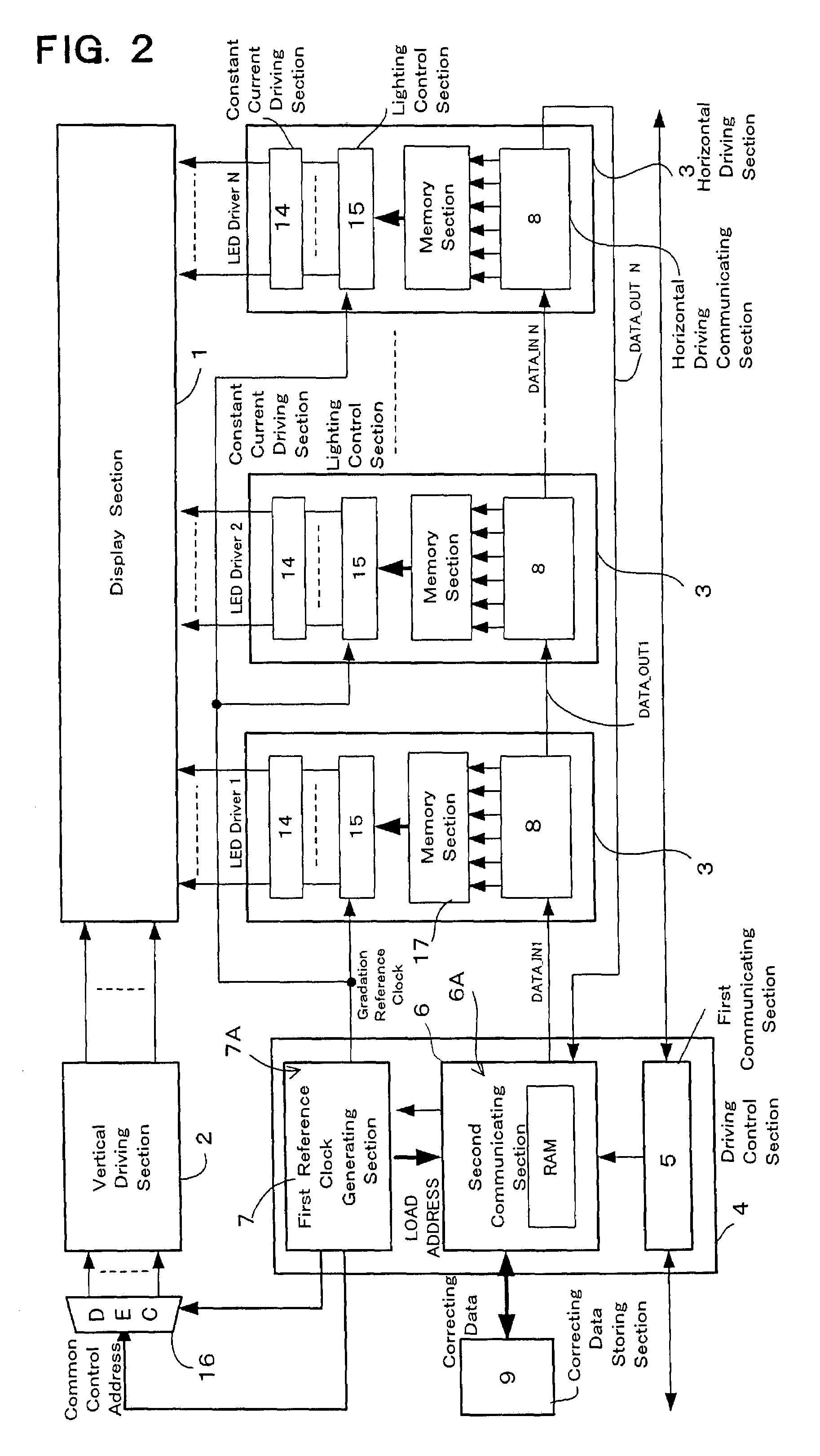
[0119]FIG. 2 is a schematic block diagram showing an embodiment of a display apparatus of this invention. The display apparatus shown in FIG. 3 has[0120](a) a display section 1 disposing a plurality of lighting elements 11 in M rows×N columns of a matrix shape,[0121](b) a vertical driving section 2 impressing current to each row of the display section 1 with selecting each row,[0122](c) horizontal driving sections 3 supplying driving current to each column of the display section 1 based on image data corresponding to the selected row,[0123](d) a driving control section 4 with a first communicating section 5, a second communicating section 6, and first reference clock generating section 7, and[0124](e) a correcting data storing section 9 storing correcting data for correcting.

[0125]Each constituting element is controlled by the driving control secti...


PUM


Abstract

Each horizontal driving section and a driving control section of a display apparatus have a data communicating function. The driving control section has a first communicating section receiving data from an external device and a second communicating section communicating data with each horizontal driving section. The second communicating section adds individual identification information for identifying each horizontal driving section to the transferred data, and transfers the data in packet format. The horizontal driving section receives the data packet for it based on the identification information, and performs current driving for a display section. The driving control section adds the individual identification information to the control data to be transferred to each horizontal driving section corresponding to connecting form of the horizontal driving sections, and transfers the control data not concerned with connecting order of the horizontal driving sections. The horizontal driving section side performs a receiving process and lighting operation.

Description

FIELD OF THE INVENTION[0001]This invention relates to a display apparatus, a display driving circuit and a method for driving a display, having a plurality of lighting elements disposed in desired arrangement such as matrix shape or the like, and more particularly to a driving circuit or the like receiving lighting data such as image data or illuminating data or the like transferred from an external device such as a video processor or the like, transferring the data in a predetermined data format to a plurality of connected driving circuits, and performing various corrections of gradation, luminance, characteristics or the like.BACKGROUND ART[0002]This application claims priority based on patent applications No. 2000-230095 and No. 2000-230624 filed in Japan, the contents of which are incorporated herein by reference.[0003]Recently, high-luminance light emitting elements, such as light emitting diodes (hereinafter, occasionally abbreviated to LEDs), have been developed for each of R...

Claims


Application Information

Patent Timeline
Patent Type & Authority Patents(United States)
IPC IPC(8): G09G5/00G09G3/20G09G3/32G09G5/18
CPCG09G3/32G09G3/2014G09G3/2018G09G5/18G09G2330/08G09G2310/0221G09G2310/0275G09G2310/0297G09G2320/0276G09G2300/026G09G3/20
Inventor NAGAI, YOSHIFUMITSUJI, RYUHEI
Owner NICHIA CORP
Why Eureka
Try Eureka