Eureka AIR delivers breakthrough ideas for toughest innovation challenges, trusted by R&D personnel around the world.

Cleat with gasket

a technology of gaskets and cleats, applied in the field of rope cleats, can solve the problems of affecting the sealing effect of the stud, so as to achieve the effect of preventing water from entering the stud

Inactive Publication Date: 2006-04-25
AMY RON
View PDF1 Cites 3 Cited by
  • Summary
  • Abstract
  • Description
  • Claims
  • Application Information

AI Technical Summary

Benefits of technology

[0008]The primary object of the invention is to provide a rope cleat for a vessel deck that, when installed, can not cause water leakage through the deck of the vessel.
[0010]Another object of the invention is to provide a rope cleat that can more easily withstand the lateral forces encountered when a rope pulls on a cleat.
[0011]Another object of the invention is to provide a means to secure other items to a deck such as fill caps, antenna mounts and the like that are installed in a similar manner to a cleat and posses similar leakage problems.

Problems solved by technology

Unfortunately, the act of tightening the nut forces the flat underside of the support structure toward the surface of the deck thereby causing any caulking material to be squeezed out or any rubber washer to be distorted and thereby not properly sealed around the stud.
Additionally, the harsh environment found in the boating world including great temperature changes, humidity changes and corrosive salt water environments can cause the caulking or the rubber washer between the cleat support structure and the deck to degrade thereby causing a potential pathway for water to travel.
The resulting water damage can require expensive and time consuming repairs.
Furthermore, if the cleat support structures are resting on a compressible gasket material such as rubber or the like, unwanted movement occurs from side loads as dock lines pull on the cleat.
A further complication in using a compressible gasket is that there is an increase of flex loads on the threaded stud fasteners and attached nuts that could result in mechanical failure causing the cleat to break away from the deck and the moored boat to drift away from its mooring.

Method used


Image

  • Cleat with gasket
  • Cleat with gasket
  • Cleat with gasket

Examples


Embodiment Construction

[0022]Detailed descriptions of the preferred embodiment are provided herein. It is to be understood, however, that the present invention may be embodied in various forms. Therefore, specific details disclosed herein are not to be interpreted as limiting, but rather as a basis for the claims and as a representative basis for teaching one skilled in the art to employ the present invention in virtually any appropriately detailed system, structure or manner.

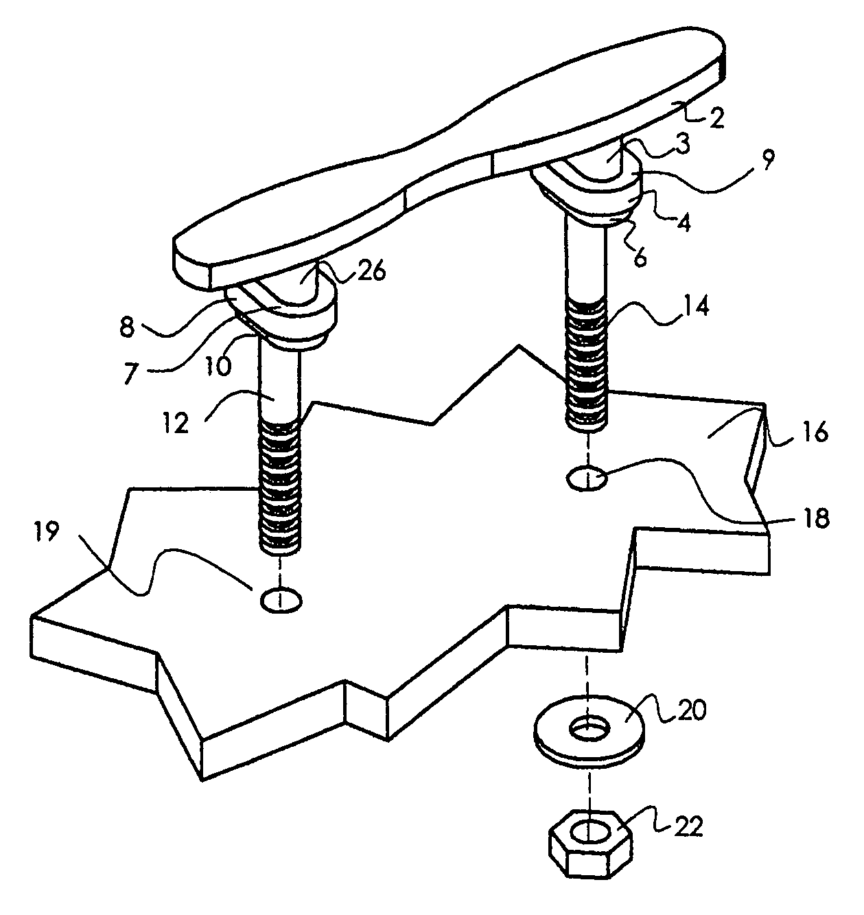
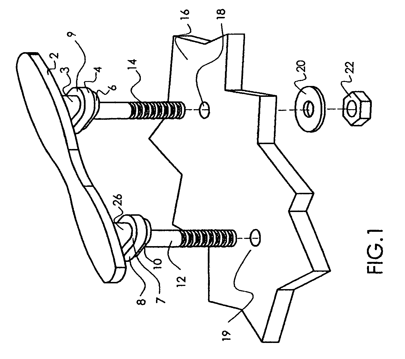
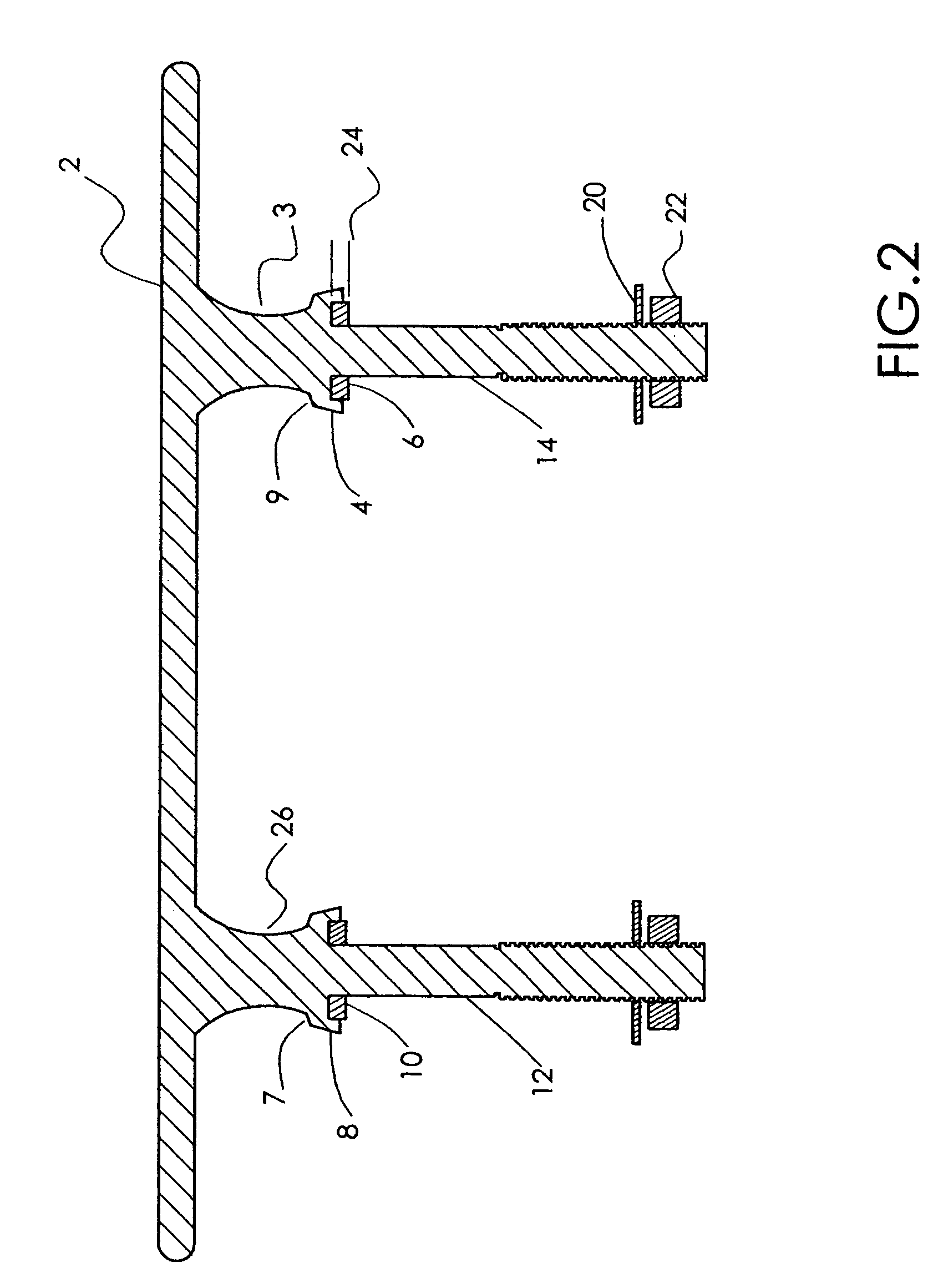
[0023]Referring now to FIG. 1 we see an exploded view of the cleat present invention. The cleat is comprised of a horizontally disposed elongate rigid bar 2 and a plurality of integral support posts 3, 26 that include a horizontally disposed plate 7,9. From the underside of plate 7,9 protrudes a threaded post 12, 14. The threaded posts 12, 14 can penetrate apertures 18, 19 and be retained by a standard nut 22 and washer 20. FIG. 2 shows a side section view where the recessed gasket 6, 10 are retained by a skirt-like perimeter caused ...


PUM


Abstract

Cleat with gasket comprising a rigid horizontally disposed elongate bar and a plurality of vertically disposed support members. The upper portion of the support member is attached to the bar. The mid portion of the support structure poses a horizontally disposed flat plate, the underside of which is recessed to receive a resilient gasket. A threaded post extends down from the underside of the recess so that it can penetrate the deck of a boat. The gasket protrudes slightly from the recessed area and is compressed in a controlled way when a nut on the treaded post is tightened forcing the flat plate down onto the deck of a boat thereby eliminating the chance of leakage through the deck.

Description

CROSS REFERENCE TO RELATED APPLICATIONS[0001]Not ApplicableSTATEMENT REGARDING FEDERALLY SPONSORED RESEARCH OR DEVELOPMENT[0002]Not ApplicableDESCRIPTION OF ATTACHED APPENDIX[0003]Not ApplicableBACKGROUND OF THE INVENTION[0004]This invention relates generally to the field of vessel cleats and more specifically to a vessel cleat with recessed gasket.[0005]Vessels such as sail boats, power boats and the like need to be restrained from drifting away from a dock when stationed at a port or the like. To this end, rope cleats are mounted to the perimeter of the deck of a standard vessel so that the boat owner can attach a rope from the dock to the vessel thereby restraining the vessel from leaving the dock.[0006]Cleats are commonly bolted to the deck of a vessel. Conventional cleats have an elongate bar that is held up a few inches by a plurality of support structures. Each support structure has a female aperture that can accept a standard bolt or has a threaded post cast into the undersi...

Claims


Application Information

Patent Timeline
Patent Type & Authority Patents(United States)
IPC IPC(8): B63B21/04
CPCB63B21/04
Inventor AMY, RON
Owner AMY RON
Why Eureka
Eureka Blog
Learn More