Vehicle fuel management system

a fuel management system and vehicle technology, applied in electrical control, combustion-air/fuel-air treatment, tractors, etc., can solve the problems of unfavorable fuel pump operation, continued full-speed operation of fuel pump, and unfavorable fuel storage and delivery, so as to achieve cost-effective control

Inactive Publication Date: 2006-06-06
UUSI
View PDF38 Cites 27 Cited by
  • Summary
  • Abstract
  • Description
  • Claims
  • Application Information

AI Technical Summary

Benefits of technology

[0010]According to one aspect of the present invention, an integrated fuel management system and method are provided that offer cost affordable controls for controlling the fuel storage and delivery in a vehicle. The fuel management system includes a fuel storage tank for storing fuel in a vehicle, and a vapor collection canister coupled to the fuel storage tank for collecting fuel vapor. A vent actuator is coupled to the vapor collection canister for venting gas from the canister during a vent operation. A purge actuator is also coupled to the vapor collection canister for purging fuel vapor from the vapor collection canister during a purge operation. A variable speed fuel pump is disposed within the fuel storage tank for delivering fuel to a fuel delivery line. The fuel management system further includes a controller provided in a module disposed in fluid communication with the fuel. The controller controls the amount of fuel pumped with the variable speed fuel pump to deliver fuel to the fuel delivery line, and further controls the purge and vent actuators to perform the purge and vent operations.

Problems solved by technology

This results in a continuous audible noise which can be noticeable to vehicle occupants, particularly when the engine is operated at low engine load demands, e.g., engine idle speed.
Continued full speed operation of the fuel pump further consumes electrical energy, which could otherwise be made available elsewhere to enhance the vehicle energy efficiency.
Additionally, the return of a large amount of excessive fuel through the regulator to the fuel storage tank may cause heating of the fuel that, in turn, creates unwanted gas vapor, which adds to evaporative emissions, and which then must be vented through a charcoal canister.
Many such fuel delivery systems are generally complex and costly.
During a fuel fill operation, for example, when the fuel storage tank is excessively filled with fuel, the fuel canister may rapidly become saturated, hence requiring a purge operation.
However, it is possible to continue to dispense incremental amounts of fuel in the fuel storage tank, thereby leading to saturation of the vapor collection canister.
Conventional fuel delivery systems rely primarily upon the engine control module to control the various fuel storage, delivery, and management functions by controlling such devices on and off, but do not provide for optimal integration of fuel delivery functions.

Method used


Image

  • Vehicle fuel management system
  • Vehicle fuel management system
  • Vehicle fuel management system

Examples


first embodiment

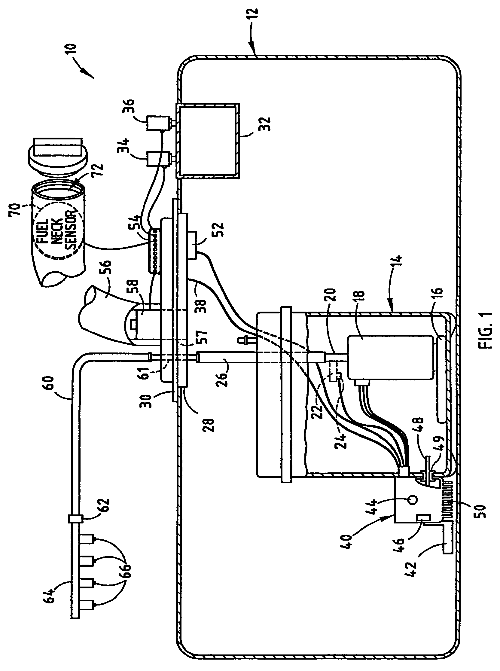
[0036]Referring to FIG. 1, the vehicle fuel management system 10 is generally illustrated for use in on-board management and control of fuel for an engine in an automotive vehicle. The vehicle fuel management system 10 integrates various fuel related functions generally associated with the fill, storage, and delivery of fuel to the engine in an automotive vehicle. The vehicle fuel management system 10 includes a fuel delivery system for delivering fuel from a fuel storage tank 12 to a fuel rail 64 associated with the vehicle engine. The vehicle fuel management system 10 also controls the fuel fill operation to fill and store fuel in the fuel storage tank 12. Further, the fuel management system 10 controls the fuel vapor vent and purge operations to vent pressurized gas and purge evaporated vapor emissions from a fuel collection canister, respectively. The various fuel related functions performed by the fuel management system 10 are integrated together and are adapted to be controlle...

second embodiment

[0062]Referring to FIG. 10, a flow sensor 124′ is shown according to a The flow sensor 124′ is shown having a vertically disposed valve assembly 502 which has a mass that experiences a force (weight) downward due to gravity. As the fuel flow increases, the fuel flow forces the valve assembly 502 upwards within the vertical cylinder, thus allowing more fuel to pass through to the outlet 510. In addition, the fuel acts as a lubricant on the sides of the valve assembly 502. Thus, the vertical arrangement of the valve assembly 502 provides a self lubricating embodiment which may also utilize weight of the valve assembly and thus reduces the bias force required by spring 506. It is also possible to eliminate the spring 506, according to this embodiment.

[0063]Accordingly, the flow sensor 124 or 124′ provides a Hall-effect flow sensor for sensing fuel flow through the return path in a vehicle fuel delivery system for use in controlling the speed of the variable speed fuel pump. The flow s...

fourth embodiment

[0064]the fuel management system 10 showing yet a further fuel delivery system is illustrated in FIGS. 11 and 12. In FIG. 11, the fuel management system 10 is shown having the fuel control module 40 disposed within the fuel storage tank 12 and connected to the fuel reservoir assembly 14. In this embodiment, the outlet 20 of the variable speed fuel pump 18 is configured to pass through a flow path 45 provided internal to the fuel control module 14 which, in turn, is connected to the fuel delivery line 26. Disposed in communication with the internal flow path 45 and module 40 is the flow sensor 124 (see FIG. 12) integrally mounted within the fuel control module 40. The flow sensor 124 monitors the rate of flow of fuel through flow passage 45 internal to the fuel control module 40. Accordingly, by employing a flow sensor 124 internal to fuel control module 40, a reduction in the wires and external components is achieved.

[0065]Referring particularly to FIG. 12, the fourth embodiment of ...


PUM


Abstract

An integrated fuel management system and method for controlling the fuel storage and delivery in a vehicle. The fuel management system includes a fuel storage tank for storing fuel in a vehicle, a vapor collection canister located within the fuel storage tank, a vent actuator coupled to the vapor collection canister for venting gas from the canister during a vent operation, and a purge actuator is coupled to the vapor collection canister for purging fuel vapor from the vapor collection canister during a purge operation. A variable speed fuel pump is disposed within the fuel storage tank for delivering fuel to a fuel delivery line for an engine. The fuel management system has a controller provided in a module disposed in communication with the fuel for controlling the amount of fuel pumped with the variable speed fuel pump to deliver fuel to the fuel delivery line and further controlling the purge and vent actuators.

Description

[0001]This is a divisional of Ser. No. 10 / 157,363 filed May 29, 2002 now U.S. Pat. No. 6,877,488BACKGROUND OF THE INVENTION[0002]The present invention generally relates to on-board fuel storage and delivery to an engine in a vehicle and, more particularly, relates to vehicle fuel management for controlling fuel storage and delivery to the engine.[0003]Automotive vehicles are typically powered by an internal combustion engine that converts the chemical energy of a fuel (e.g., gasoline) to mechanical energy for driving a powertrain which, in turn, propels the vehicle via road wheels. Additionally, some of the mechanical energy is also converted to electrical energy via an alternator and is stored in a battery and used to power various electrically operated devices. Vehicles are being equipped with increasing numbers of electrically powered devices, all of which consume energy. Thus, it is desirable to enhance the efficiency of the electrically powered devices in order to maximize the ...

Claims


Application Information

Patent Timeline
Patent Type & Authority Patents(United States)
IPC IPC(8): F02M33/02B60K15/035F02D41/00F02D41/26F02D41/30F02D41/38F02M25/08F02M37/10
CPCB60K15/03504B60K15/03519F02D41/0032F02M37/106F02D41/266F02D41/3082F02M25/08F02M25/089F02M37/0082F02D41/0045B60K2015/0319B60K2015/03557F02D41/003F02D41/3809
Inventor WASHELESKI, JOHNPERRIN, RANDALL L.MITCHELL, JOHN E.
Owner UUSI
Why Eureka
Try Eureka