
Bendable extension arm

a technology of extension arm and bendable wire, which is applied in the direction of wing knob, mechanical control device, instruments, etc., can solve the problems of corroding joints, affecting reducing the service life of the wing, so as to prevent overbending of the stiffening wire

Inactive Publication Date: 2006-09-05
MCCAULEY TOOLS
View PDF19 Cites 30 Cited by
  • Summary
  • Abstract
  • Description
  • Claims
  • Application Information

AI Technical Summary

Benefits of technology

[0004]The present invention provides a bendable extension arm. A stiffening wire having a first end and a second end is connected at its first end to a wire receptor and at its second end to another wire receptor. A sheath covers the stiffening wire and prevents over bending of the stiffening wire. In a preferred embodiment, attachment devices are connected to the wire receptors. For example, in one embodiment a paint brush is connected to one of the wire receptors and an extension pole is connected to the other wire receptor. In another preferred embodiment, the bendable extension arm is used as a bendable handle. The user can grab the bendable handle at one end and attach an attachment device to the other end of the bendable handle. The bendable handle can be bent as desired by the user.

Problems solved by technology

Loosening the joint, setting the desired angle, and then retightening the joint can be a time consuming and tedious process.
Also, the joints can corrode and fail over time.

Method used


Image

  • Bendable extension arm
  • Bendable extension arm
  • Bendable extension arm

Examples


first preferred embodiment

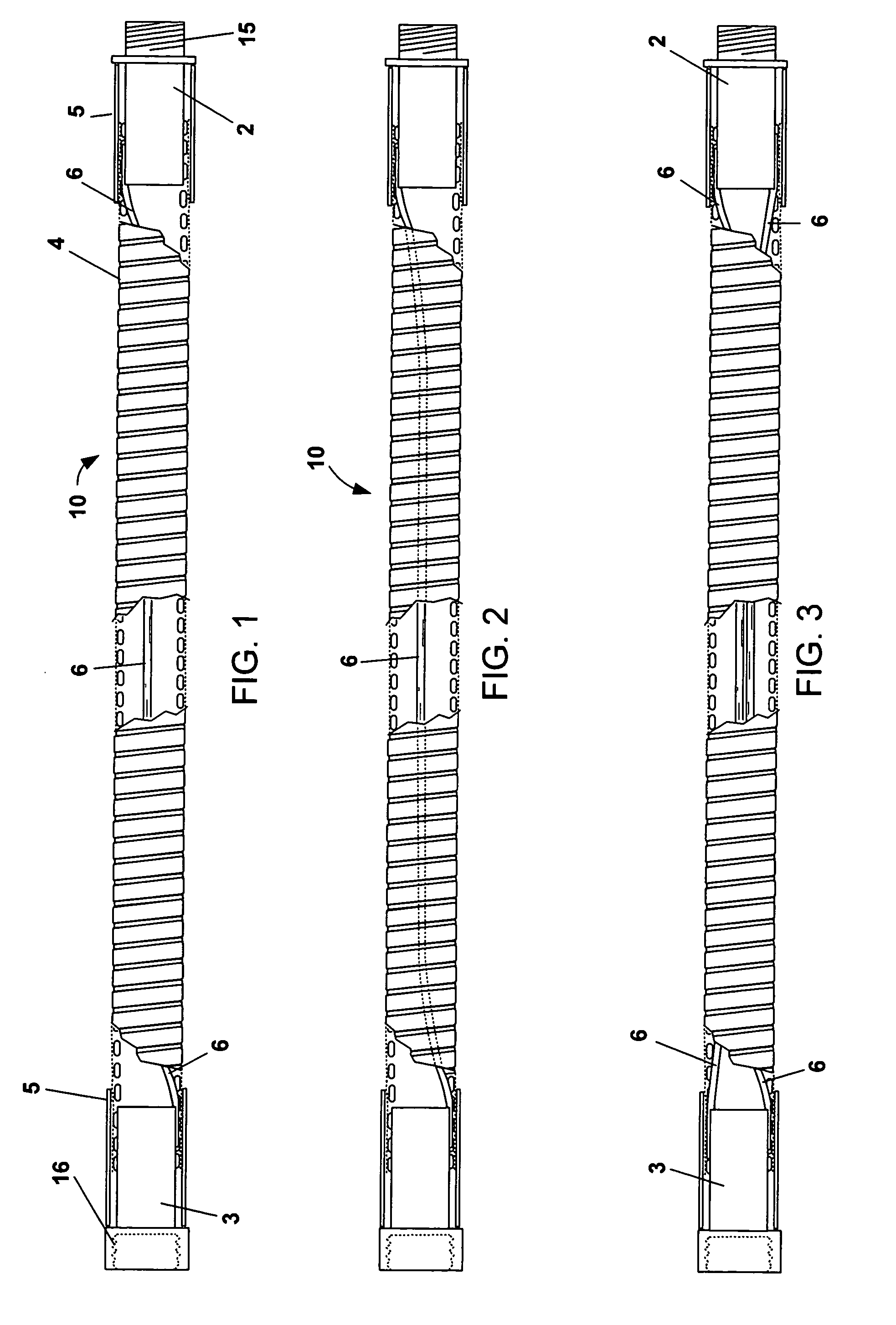
[0016]FIG. 1 shows a first preferred embodiment of bendable extension arm 10. Stiffening wire 6 is connected to male wire receptor coupler 2 and female wire receptor coupler 3. External sheath 4 covers wire 6 and the internal ends of wire receptor couplers 2 and 3. In the preferred embodiment shown in FIG. 1, ferrules 5 are crimped over sheath 4, wire 6 and the internal ends of wire receptor couplers 2 and 3, thereby attaching sheath 4 and wire 6 to wire receptor couplers 2 and 3.

Stiffening Wire

[0017]In the preferred embodiment, stiffening wire 6 is 10 gage galvanized steel wire. In the preferred embodiment, wire 6 is approximately 15–18 inches long. Wire 6 has sufficient stiffness to allow a user of ordinary strength to easily bend bendable extension arm 10 to the desired shape while at the same time holding the desired shape while bendable extension arm 10 is being utilized. For example, FIG. 8 shows bendable extension arm 10 attached to the end of extension pole 12. Paint brush 1...

second preferred embodiment

[0021]A second preferred embodiment is shown inFIG. 3. Two wires 6 are connected to wire receptor couplers 2 and 3. The utilization of two wires increases the strength and stiffness of bendable extension arm 10.

third preferred embodiment

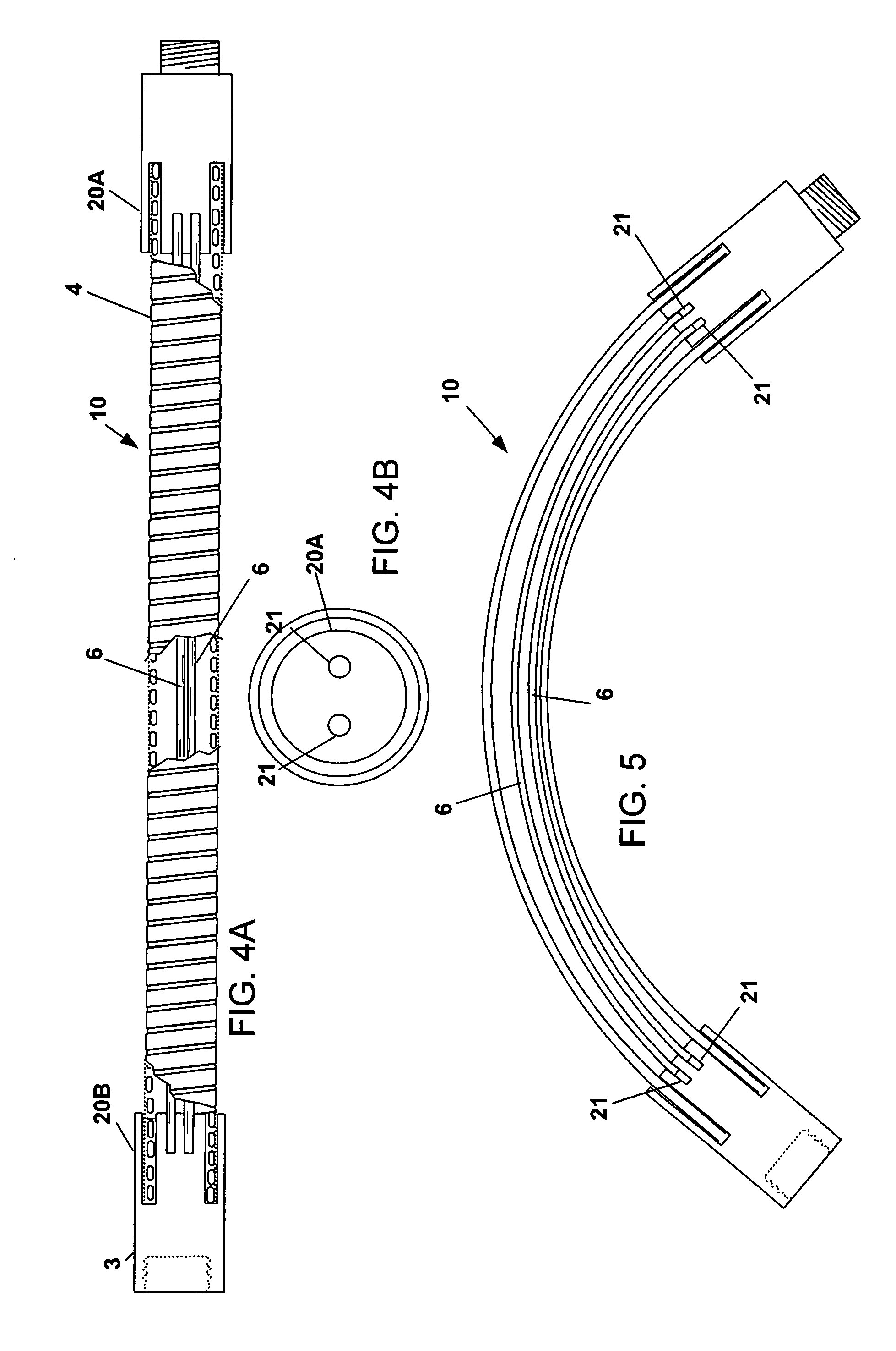
[0022]A third preferred embodiment is shown in FIGS. 4A–5. The third preferred embodiment includes wire receptor couplers 20A and 20B. Preferably, wire receptor couplers 20 are aluminum and are crimped onto sheath 4 in a fashion similar to that described above. Wire receptor couplers 20A and 20B include circular cutouts 21 (FIG. 4B) for receiving wires 6.

[0023]In the third preferred embodiment wires 6 slide back and forth in wire receptor couplers 20A and 20B as bendable extension arm 10 is bent. For example, as shown in FIG. 4A, when bendable extension arm 10 is straight, wires 6 extend to the ends of cutouts 21 (FIG. 4B). However, when bendable extension arm 10 is bent (FIG. 5), wires 6 slide part of the way out of cutouts 21. By allowing wires 6 to slide along cutouts 21, the stiffness of arm 10 is decreased making it easier for the user to bend bendable extension arm 10.


PUM


Abstract

A bendable extension arm. A stiffening wire having a first end and a second end is connected at its first end to a wire receptor and at its second end to another wire receptor. A sheath covers the stiffening wire and prevents over bending of the stiffening wire. In a preferred embodiment, attachment devices are connected to the wire receptors. For example, in one embodiment a paint brush is connected to one of the wire receptors and an extension pole is connected to the other wire receptor. In another preferred embodiment, the bendable extension arm is used as a bendable handle. The user can grab the bendable handle at one end and attach an attachment device to the other end of the bendable handle. The bendable handle can be bent as desired by the user.

Description

BACKGROUND OF THE INVENTION[0001]Extension arms are known. Painters commonly use extension arms to reach high areas on a wall or a tall ceiling. Also, extension arms are attached between the shower plumbing and the shower head so that the shower head can be positioned to meet the tastes of the individual taking a shower.[0002]Prior art extension arms have adjustable knuckle joints that allow the user to adjust the angle of the extension. Loosening the joint, setting the desired angle, and then retightening the joint can be a time consuming and tedious process. Also, the joints can corrode and fail over time.[0003]What is needed is a better extension arm.SUMMARY OF THE INVENTION[0004]The present invention provides a bendable extension arm. A stiffening wire having a first end and a second end is connected at its first end to a wire receptor and at its second end to another wire receptor. A sheath covers the stiffening wire and prevents over bending of the stiffening wire. In a prefer...

Claims


Application Information

Patent Timeline
Patent Type & Authority Patents(United States)
IPC IPC(8): A47B95/02A46B5/00E05B1/00
CPCA46B5/0062A46B5/0075A46B5/0079A46B2200/202Y10T16/4713Y10T74/20738Y10T16/4719Y10T16/491Y10T16/44
Inventor MCCAULEY, PATRICK
Owner MCCAULEY TOOLS
Learn More