Detachable aneurysm neck closure patch

a neck closure and aneurysm technology, applied in the field of detachable aneurysm neck closure patch, can solve the problems of difficult or impossible retrieval of material, difficult placement of mixture, and particularly acute medical risk of aneurysms

Inactive Publication Date: 2006-10-31
STRYKER EURO OPERATIONS HLDG LLC +1
View PDF25 Cites 230 Cited by
  • Summary
  • Abstract
  • Description
  • Claims
  • Application Information

AI Technical Summary

Benefits of technology

[0023]This invention includes an implantable medical device useful for retaining other occlusion device at an occlusion site, such as an aneurysm, and related methods of introducing and installing that implantable retainer at the occlusion site. Combinations of the retainer device and its included vaso-occlusive material or device are also an aspect of the invention as are combinations of the retainer device and its delivery components. In particular, the invention involves an implantable retainer, which is deliverable through an elongated tubular delivery device such as a vascular catheter. The assemblage includes an implantable retainer which is placed just inside or just outside the aneurysm mouth and allowed to remain at that aneurysm mouth. The assembly includes a tubular delivery member to which it is attached by an electrolytically severable joint. In general, the implantable retainer component may either be mounted upon and extend from the distal end of the tubular delivery member or may be delivered from the lumen of the delivery.
[0024]The joint itself is desirably an electrolytically severable upon application of a suitable current to the joint, typically by use of a conductor wire which may be placed in the wall of the delivery member. The joint is comparatively more electrolytically dissolvable or erodible when a current is applied than are any of the rest of the components that surround or deliver it. The aneurysm patch itself typically includes a number of radially extending elements shaped to support a soft fabric generally attached to the radial elements. The radial elements have a primary shape during delivery, e.g., when inside the delivery tubular member, and then assume a secondary shape upon exit from the distal end of that delivery tubular member. Once the aneurysm patch subassembly containing the array elements is in place, the vaso-occlusive device, e.g. vaso-occlusive coils, may be introduced into the aneurysm either through the small tubular member to which the array members are attached or, if the array members do not have a mesh covering, through the open area found at the neck of the aneurysm.

Problems solved by technology

Often these aneurysms are the site of internal bleeding and stroke.
Their use is fraught with problems in that placement of the mixture is quite difficult.
The material is also difficult or impossible to retrieve once it has been placed in the vasculature.
As noted above, aneurysms present particularly acute medical risk due to the dangers of potential rupture of the thin wall inherent in such aneurysm.
After, or perhaps, during, delivery of such a coil into the aneurysm, there is a specific risk that a portion of the coil might migrate out of the aneurysm entrance zone and into the feeding vessel.
The presence of such a coil in that feeding vessel may cause the highly undesirable response of causing an occlusion there.
Also, there is a quantifiable risk that the blood flow in the vessel and aneurysm may induce movement of the coil farther out of the aneurysm, resulting in a more developed embolus in the patent vessel.
One type of aneurysm, commonly known as a “wide neck aneurysm” is known to present particular difficulty in the placement and retention of vaso-occlusive coils.
Furthermore, vaso-occlusive coils lacking substantial secondary shape strength may be difficult to maintain in position within an aneurysm no matter how skillfully they are placed.
There are few disclosed devices for maintaining the presence of vaso-occlusive coils within an aneurysm.

Method used


Image

  • Detachable aneurysm neck closure patch
  • Detachable aneurysm neck closure patch
  • Detachable aneurysm neck closure patch

Examples


Embodiment Construction

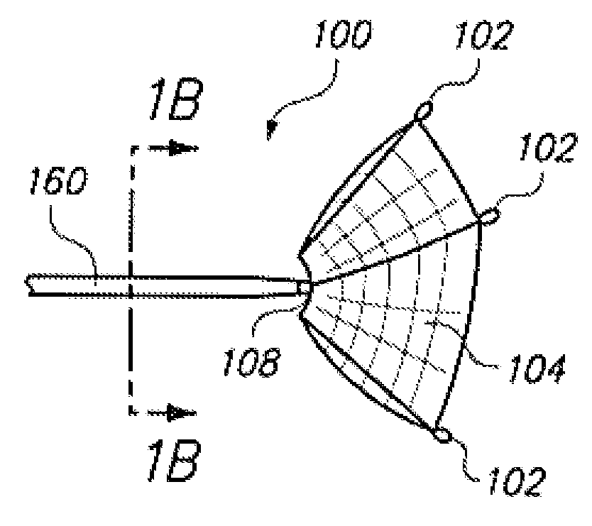
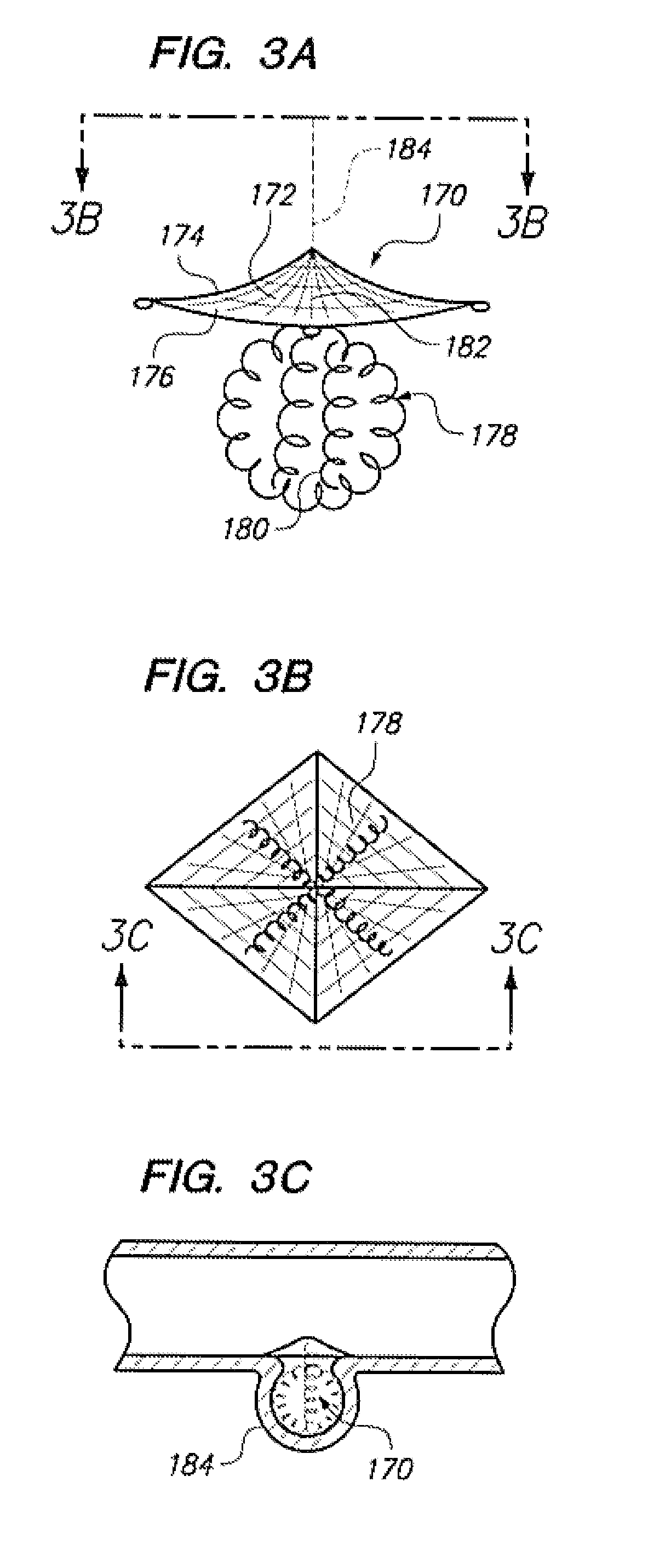
[0034]This invention relates to a device and a procedure for stabilizing the position and, usually, the structure of vaso-occlusive devices which are placed in a target occlusion site, usually an aneurysm. The retaining devices or patches prevent the potential migration of those one or more occlusive devices (e.g., helically wound coils) from that target occlusion site, by forming a barrier at the entrance zone to the aneurysm where it meets a feeding vessel.

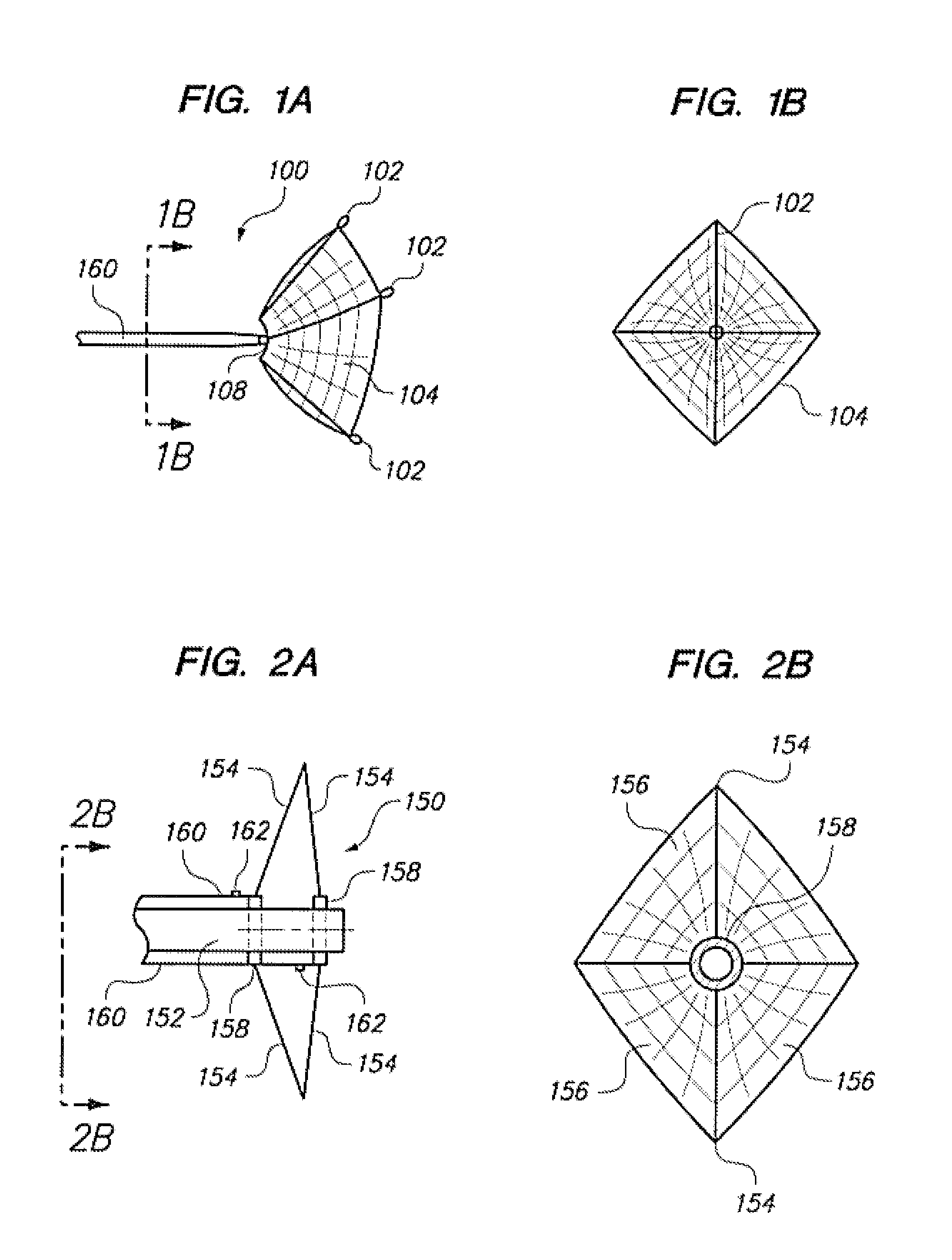
[0035]FIG. 1A shows in side view one variation of an aneurysm patch (100) made according to this invention. Specifically, FIG. 1A shows an aneurysm patch (100) having a number of radially extending members (102), which may have blunted tips to prevent trauma to the arteries in which they are placed. A slight bend may be noticed in the radially extending members (102). This bend helps release the aneurysm patch (100) from the delivery catheter upon deployment. As will be shown below in more detail, the radially extending members ...


PUM


Abstract

This is a device for bridging the neck of either an aneurysm in the vasculature and stabilizing the presence of vaso-occlusive devices (such as helically wound coils) in that aneurysm. The closure patch may be delivered either from the exterior of the distal end of a catheter or delivered from the catheter lumen. It is preferably implanted by the severance of an included electrolytically severable joint. The retainer assembly itself typically has a number of radially projecting elements which are, in turn, attached to a scrim-like fabric, preferably collagen-coated Dacron, extending among the various radially projecting elements. The closure patch is intended to be resident within the aneurysm after it is deployed. After deployment, the aneurysm may be at least partially filled with vaso-occlusive devices such as helically wound coils.

Description

CROSS-REFERENCE TO RELATED APPLICATIONS[0001]This application is a continuation of U.S. patent application Ser. No. 09 / 148,411 filed Sep. 4, 1998, now abandoned.FIELD OF THE INVENTION[0002]This invention is a device for bridging the neck of either an aneurysm in the vasculature and stabilizing the presence of vaso-occlusive devices (such as helically wound coils) in that aneurysm. The patch may be ccombined with a component residing within the aneurym for providing form to the aneurysm or for anchoring the assembly to the aneurysm. The closure patch may be delivered either from the exterior of the distal end of a catheter or delivered from the catheter lumen. It is preferably implanted by the severance of an included electrolytically severable joint. The retainer assembly itself typically has a number of generally radially projecting elements which are, in turn, attached to a scrim-like fabric extending among the various radially projecting elements. The closure patch may be residen...

Claims


Application Information

Patent Timeline
Patent Type & Authority Patents(United States)
IPC IPC(8): A61B17/00A61B17/12A61B19/00
CPCA61B17/12022A61B17/12113A61B17/1214A61B17/12172A61B17/0057A61B19/54A61B2017/12063A61B90/39
Inventor ABRAMS, ROBERT M.ENGELSON, ERIK T.PEDERSEN, JOHN B.CARRISON, HAROLD F.
Owner STRYKER EURO OPERATIONS HLDG LLC
Why Eureka
Try Eureka