Pipeline field joint coating for wet insulation field joints

a field joint and pipeline technology, applied in the field of field joint coating, can solve the problems of difficult design of field joint, difficult to meet the requirements of field joint, and inability to use dissimilar materials, etc., to achieve the effect of preventing any hydrolysis or breakdown of infill material and sufficient strength

Inactive Publication Date: 2008-04-03
OFFSHORE JOINT SERVICES
View PDF19 Cites 15 Cited by
  • Summary
  • Abstract
  • Description
  • Claims
  • Application Information

AI Technical Summary

Benefits of technology

[0012] Briefly, the present invention provides a new and improved field joint coating and infill of the uncoated field joint area of welded pipelines / flowlines otherwise covered along their lengths with thermoplastic wet insulation for subsequent placement in bodies of water. The present invention utilizes the fast gelling nature of thermosetting systems, or other suitable fillers, coupled with a fully fused thermoplastic outer sheath. The outer sheath is fully fused circumferentially to the parent coating at each end of the field joint and an outer closure patch is then fused to the sheath over the joining area and / or injection ports. This totally seals the filler material from direct contact with water, preventing any water ingress reaching the pipe surface and hence preventing any hydrolysis or breakdown of the infill material. By use of a fast setting or solid infill material, the system gains sufficient strength almost immediately to withstand the rigors of handling during the lay operation.

Problems solved by technology

However, in the case of thick wet insulation systems the use of anodes as a secondary anticorrosion system can be impractical.
However, in the case of thermoplastic insulation, the design of field joint is more complicated.
The use of fast setting polyurethane was thought feasible, but the use of dissimilar materials is often problematic.
The dissimilar materials means that the quality of bond is questionable and may lead to breakdown of the interface bond and hence, water ingression down the interface chamfer to the pipe wall surface is possible.
This in turn would subject the polyurethane to hot water at the pipe interface which in turn could then attack the polyurethane and cause subsequent failure of the joint.
This type of system is slow, in that it takes several hours for the infill to fully solidify.
As a consequence, this type of system is not compatible with many offshore deep water pipe lay methods.

Method used


Image

  • Pipeline field joint coating for wet insulation field joints
  • Pipeline field joint coating for wet insulation field joints
  • Pipeline field joint coating for wet insulation field joints

Examples


Embodiment Construction

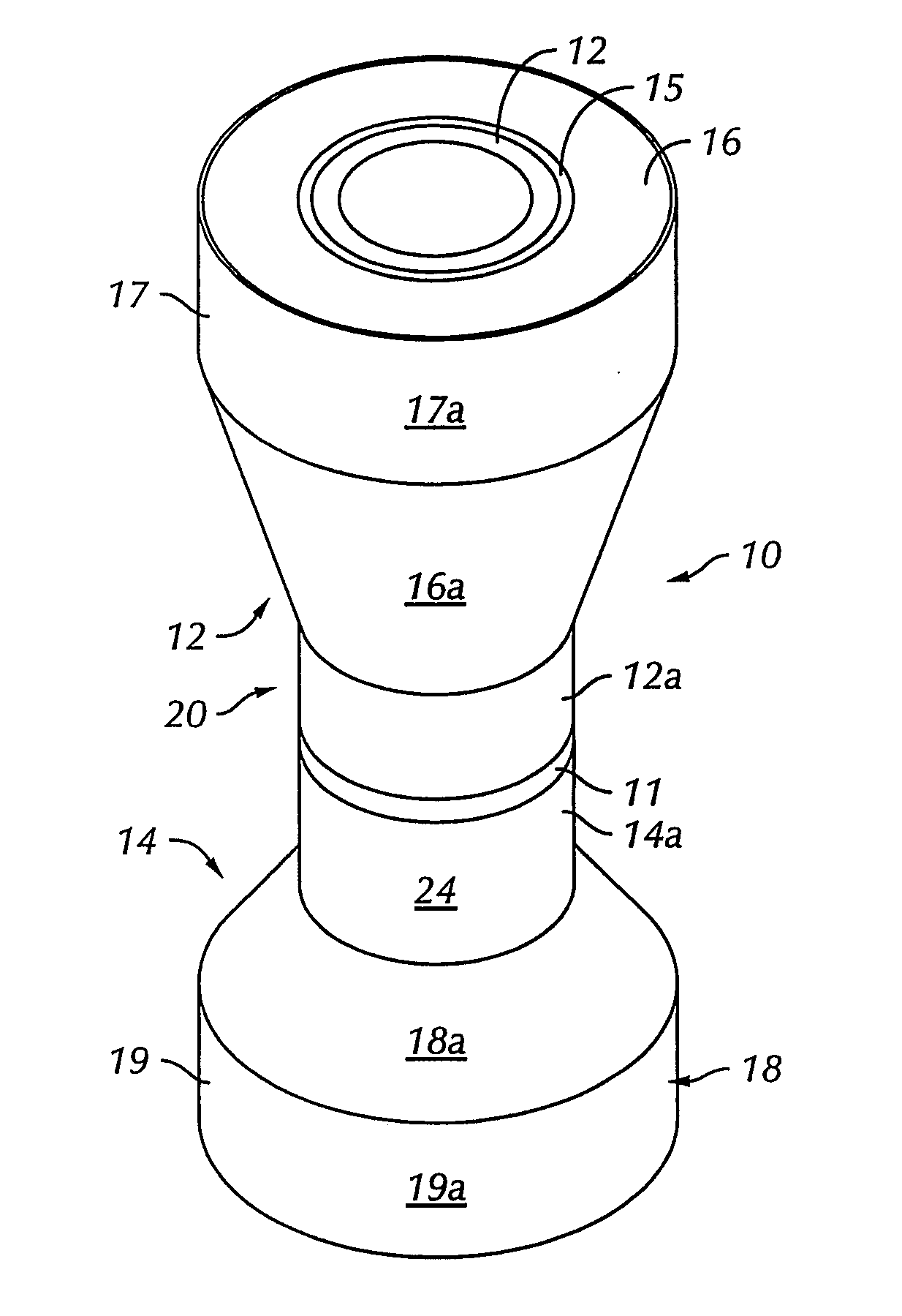
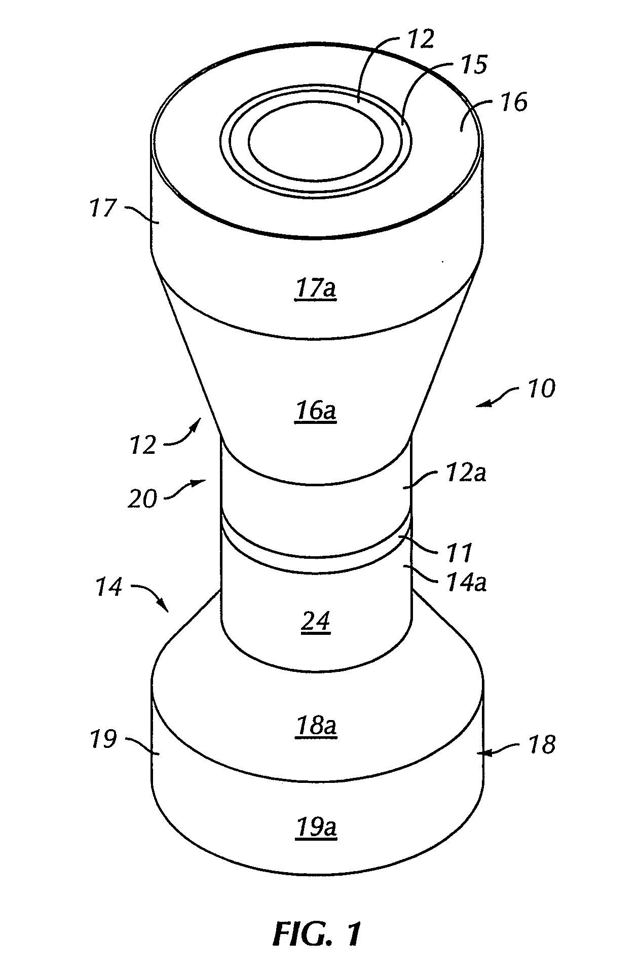
[0025] In the drawings, a pipeline 10 is shown (FIG. 1) formed by welding two pipe sections 12 and 14 which are covered by a parent coating 16 and 18, respectively. As shown at 11, the pipe sections. The pipeline 10 is typically one being laid in a relatively deep body of water and is thus shown extending generally in a vertical direction in which the pipeline 10 moves downwardly from a pipe laying barge, J-lay equipment or other suitable vessel into the body of water. It should be understood that the present invention may also be used in connection with S-lay pipeline methods or with reel lay installations, as well. Thus, the pipeline 10 may also extend generally horizontally during the pipe laying operation.

[0026] The parent coatings 16 and 18 associated with the pipe sections 12 and 14, respectively, are formed from a suitable thickness of insulated polymer, such as polypropylene, encased within an outer coat material or cover 17 and 19, respectively, also typically of polypropy...


PUM

PropertyMeasurementUnit
lengthsaaaaaaaaaa
surface areaaaaaaaaaaa
pressureaaaaaaaaaa

Abstract

Thermoplastic wet insulation field joints for pipelines in bodies of water utilize the fast gelling nature of thermosetting systems, or other suitable fillers, coupled with a fully fused thermoplastic outer sheath for protecting the pipe joint from water contact. The outer sheath is fully fused circumferentially to the parent coating at each end of the field joint, and an outer closure patch is then fused to the sheath over the joining area and / or injection ports. This totally seals the filler material from direct contact with water, preventing water ingress from reaching the pipe surface. Hydrolysis of the infill material is thus also prevented. By use of a fast setting or solid infill material the system gains sufficient strength almost immediately to withstand the rigors of handling during the lay operation.

Description

REFERENCE TO RELATED APPLICATIONS [0001] This application claims the benefit of U.S. Provisional Patent Application Ser. No. 60 / 848,467 which was filed Sep. 29, 2006.BACKGROUND OF THE INVENTION [0002] 1. Field of the Invention [0003] The present invention relates to field joint coating and infill of the uncoated area of welded pipelines / flowlines for subsequent placement, such as being laid in bodies of water, entrenched or buried or the like. [0004] 2. Description of the Related Art [0005] As offshore oil and gas recovery goes into sub sea formations in deeper bodies of water, wells in these formations are producing higher temperature hydrocarbon products at much higher pressures. The wells in deeper bodies of water have usually been located further out from host processing facilities and the subsequent connecting flowlines and pipelines between the wells and the processing facilities have become longer. The deeper water depths and longer connecting pipelines and flowlines have mea...

Claims


Application Information

Patent Timeline
Patent Type & Authority Applications(United States)
IPC IPC(8): F16L11/12
CPCF16L58/181F16L58/1063B29C33/0016B29C33/28B29C33/40B29C67/246B29L2023/225B29C65/10B29C65/103B29C65/1412B29C65/1432B29C65/1467B29C65/4815B29C65/5042B29C66/0242B29C66/0384B29C66/1122B29C66/4322B29C66/5326B29C66/73921B29C66/8242B29C66/8324B29C66/91655B29C66/942B29C63/06B29C66/912B29K2075/00B29C66/7392B29C66/71B29C66/8221B29C66/73161B29C66/496B29C66/72321B29C66/727B29K2077/00B29K2063/00B29K2027/18B29K2023/12B29K2023/06
Inventor DUNCAN, JOSEPH C.
Owner OFFSHORE JOINT SERVICES
Why Eureka
Try Eureka