Endpoint event processing system

a processing system and event technology, applied in the field of data communication, can solve the problems of limited capacity, slow and intrusive to customers, and expensive and time-consuming process types, and achieve the effects of reducing the cost of processing

Active Publication Date: 2006-12-05
HUNT TECH INC
View PDF41 Cites 100 Cited by
  • Summary
  • Abstract
  • Description
  • Claims
  • Application Information

AI Technical Summary

Problems solved by technology

For example, electric companies are migrating from costly and time-consuming manual methods of determining the amount of power consumed by customers of the power company.
This type of process was costly, slow, and intrusive to their customers.
Other remote meter reading and data communication systems that use modems or radio frequency signals also can communicate with only one endpoint at a time and thus also have limited capacity.
For example, the capacity of such systems is limited because the concentrator (or other central processing system if modems or RF are used) can receive signals from only one endpoint at a given time.
This limitation provides a bottleneck that limits the processing power and flexibility of the system.
Additionally, it limits the number of endpoints that the concentrator can communicate within a 24-hour period and hence limits the number of endpoints that can be connected downstream from any given concentrator.
The systems also have little scalability.
This limitation is caused by two factors including the limited number of endpoints that can be connected downstream from a concentrator and by the manual programming required every time that an endpoint is added to the system.
This polling is slow and consumes processing and communication resources.
Furthermore, current systems generally do not have the capability of reestablishing communication between an endpoint and an alternative concentrator if the communication link between the concentrator and the endpoint is disconnected by intentionally taking the substation off line, through a power failure.

Method used


Image

  • Endpoint event processing system
  • Endpoint event processing system
  • Endpoint event processing system

Examples


Embodiment Construction

[0025]Various embodiments of the present invention will be described in detail with reference to the drawings, where like reference numerals represent like parts and assemblies throughout the several views. Reference to various embodiments does not limit the scope of the invention, which is limited only by the scope of the claims attached hereto. Additionally, any examples set forth in this specification are not intended to be limiting and merely set forth some of the many possible embodiments for the claimed invention.

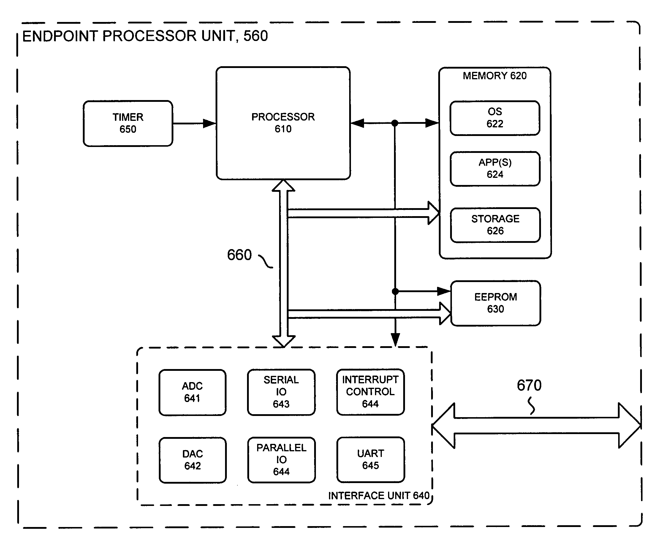
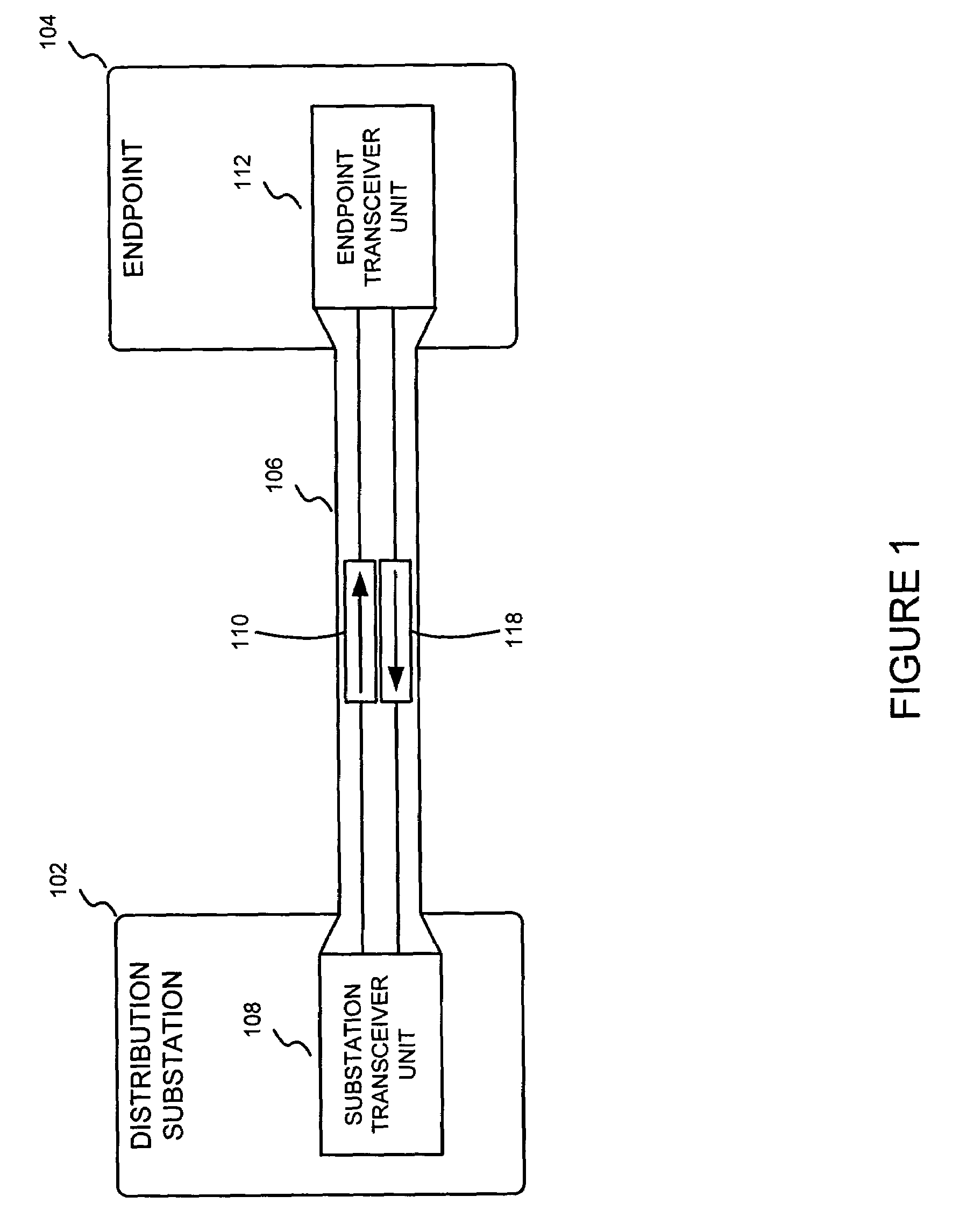
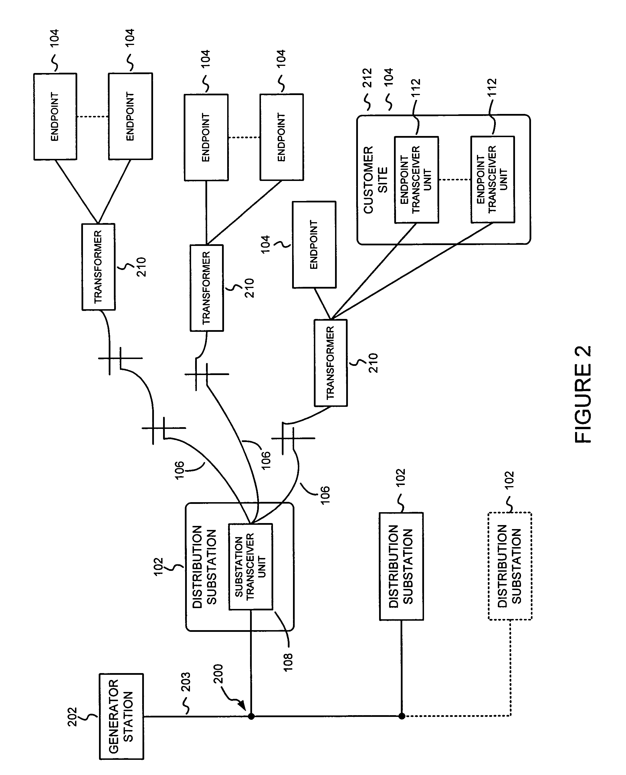
[0026]Briefly stated, an endpoint is configured for communication with a distribution substation. The endpoint includes a transceiver unit that is configured to receive command signals form the distribution substation, and provide FSK modulated signals to the substation via a power-line. The transmitter includes a resonant circuit and a half-bridge driver that are configured to drive square-wave modulated signals on the power-line to generate the FSK signal. The recei...


PUM


Abstract

An endpoint processor includes a processor block, a timer block, a memory block, and analog-to-digital converter. The timer block is arranged to provide a time based signal to the processor block. The memory block cooperates with the processor block. The analog-to-digital converter is arranged to provide an interface between an analog signal and the processor block. The analog signal includes encoded data from a power signal. The processor block is arranged to control a sampling rate that is associated with the analog-to-digital converter such that the analog signal is down-converted as an under-sampled signal. The processor block is arranged to extract the encoded data from the down-converted signal by executing a digital signal processing algorithm that is stored in the memory block. The digital signal processing algorithm is arranged to reject fundamental and harmonic frequencies that are associated with a power-line frequency that is associated with the power signal.

Description

REFERENCE TO COPENDING APPLICATIONS[0001]The present application is being filed concurrently with U.S. patent application Ser. No. 10 / 626,495, which is entitled Data Communication Over Power Lines, U.S. patent application Ser. No. 10 / 627,397, which is entitled Endpoint Receiver System, U.S. patent application Ser. No. 10 / 627,587, which is entitled Endpoint Transmitter and Power Generation System, U.S. patent application Ser. No. 10 / 626,465, which is entitled Power Line Communication System Having Time Server, and U.S. patent application Ser. No. 10 / 626,496, which is entitled Locating Endpoints In A Power Line Communication System, the entire disclosures of which are hereby incorporated by reference.TECHNICAL FIELD[0002]This invention relates generally to data communications. More particularly, the present invention is related to an event processing system in an endpoint.BACKGROUND[0003]As is true with most companies, utility companies are striving to reduce overhead costs, while pro...

Claims


Application Information

Patent Timeline
Patent Type & Authority Patents(United States)
IPC IPC(8): H04M11/04G06F1/26
CPCH04B3/54G01D4/002H04B2203/5416H04B2203/542H04B2203/5466H04B2203/5483Y02B90/241Y04S20/32H02J13/002H02J13/00007H02J13/00034Y02B90/20Y04S20/30
Inventor FLEN, ROLF J.HAUG, STUART L.RUOHONIEMI, MATTHEW DAVID
Owner HUNT TECH INC
Why Eureka
Try Eureka