Lighted ultrasonic handpiece and color code grip system

a technology of ultrasonic handpieces and color codes, which is applied in the field of medical or dental handpieces, can solve the problems that no prior art provides a light path through the insert grip to guide remotely generated light to the tip of the scaler, and achieves the effects of less stress on the clinical setting, easy gripping by the operator, and no muscle fatigue or cramping

Inactive Publication Date: 2006-12-19
FEINE JAMES MR
View PDF11 Cites 17 Cited by
  • Summary
  • Abstract
  • Description
  • Claims
  • Application Information

AI Technical Summary

Benefits of technology

[0007]The improved lighted ultrasonic dental scaling insert features a scaling tip, a velocity transducer connected to said scaling tip, an ultrasonic stack connected to said velocity transducer inserted through a grip adapted for connection with a dental scaling handpiece of the present invention. An interchangeable grip sheath can be ergonomically form fitted to more easily allow the operator to grip the ultrasonic device for long periods of time without muscle fatigue or cramping. Additionally, the interchangeable grip sheath may be color coded to permit the operator to readily identify a preferred handpiece from amongst a number of similar designed handpieces. This ability to visually determine the instrument being accessed by virtue of the color coding and the ability to use an ergonomically designed sheath adaptable to the hand of the operator fosters a less stressful clinical setting for both the dental technician and the patient.
[0008]The light source terminus in the handpiece abuts the translucent grip body and is connected to a light transmission cable permitting the transmission through the terminus into the interior of the grip covered by the sheath. A light source, which may be switched on or off and regulated to increase or decrease light intensity through the light transmission cable provides illumination through cable to the light source terminus. As previously noted, an ergonomic resilient and opaque sheath is retained over the translucent grip body to permit comfortable use of the ultrasonic device and also blocks ambient light from escaping from the translucent grip at any point except the distal end of the grip adjacent the tip.
[0009]Alternatively, the

Problems solved by technology

Although various prior art devices disclosed mounting a light or light source in the handpiece, so far as known to applica

Method used


Image

  • Lighted ultrasonic handpiece and color code grip system
  • Lighted ultrasonic handpiece and color code grip system
  • Lighted ultrasonic handpiece and color code grip system

Examples


Embodiment Construction

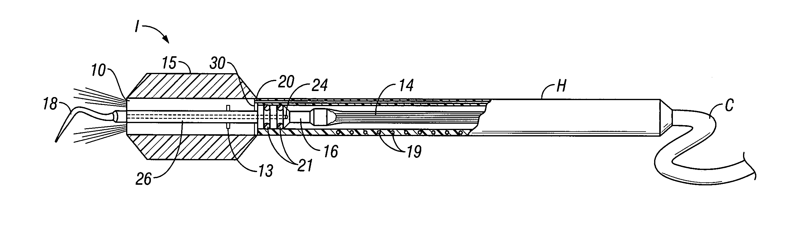
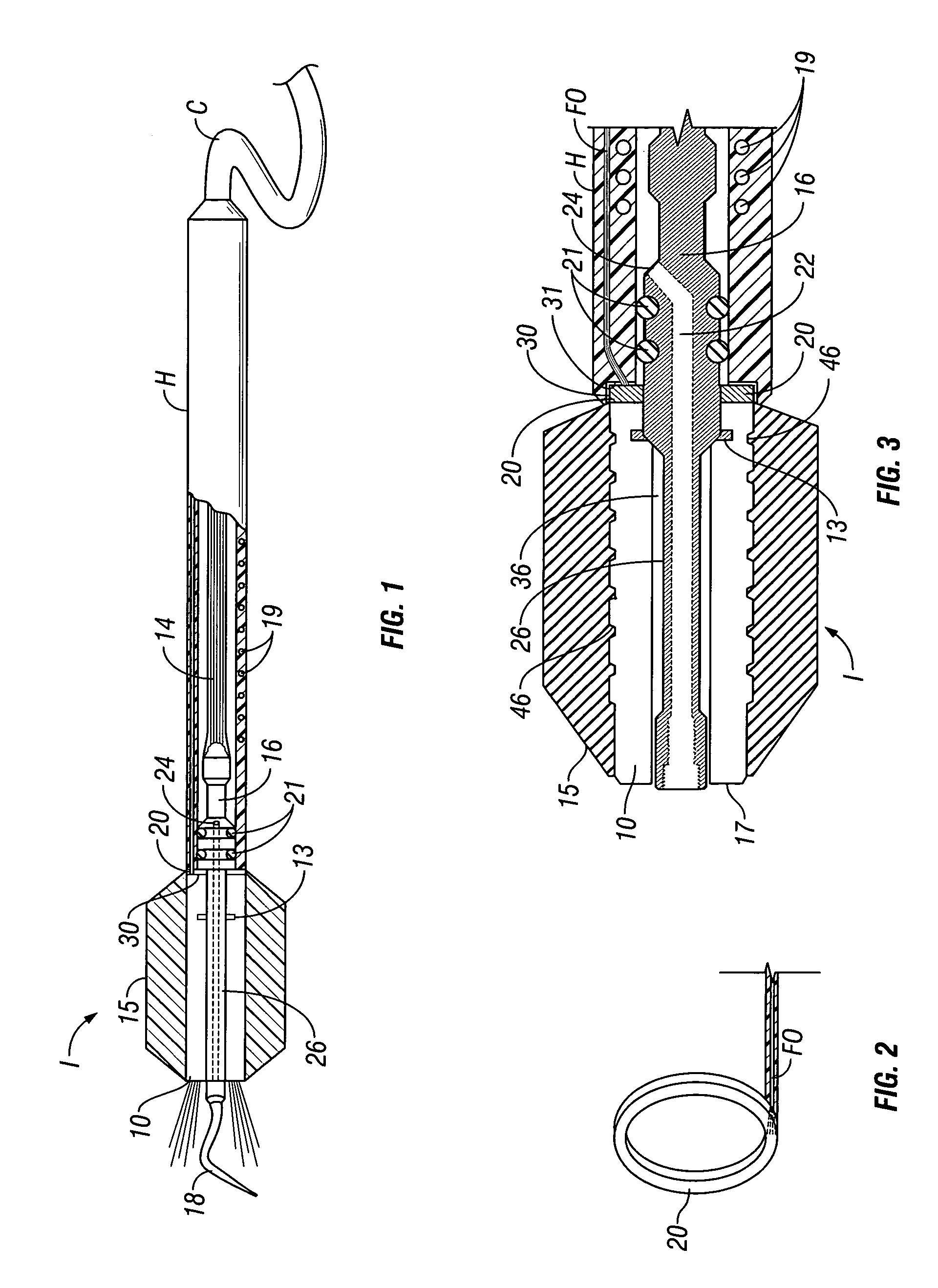
[0034]The present invention relates to a dental scaling insert providing a translucent path from a light source to the end of the handpiece through a translucent grip covered by an ergonomically designed resilient sheath. In a preferred embodiment shown in FIG. 1, insert system I is comprised of a magnetostrictive stack 14 typically formed of nickel or nickel alloy plates in a manner well known to those skilled in this art, which are soldered together and which respond to electrical energy supplied by coil 19 encircling stack 14 in the handpiece H. Stack 14 is connected to a velocity transducer 16 which is connected to a scaling tip 18 and which is covered with grip 10. Grip 10 is formed from two segments or pieces of high grade plastic, for example, such as a polycarbonate, that provide a profile on their interior surface to retain the velocity transducer 16. In this embodiment, one or more teeth 13 are provided on the exterior lateral surfaces of the velocity transducer 16 to prev...


PUM


Abstract

The present invention relates to a dental scaling translucent insert which provides a coaxially aligned light adjacent the distal end of such insert for illuminating the tip of the dental scaler which light may be provided by light emitting from a fiber optic light guide from a light source located remotely from the tip. The light provided can also be used to view through a camera lens system located in translucent insert to provide a clear unobstructed view of the work at the tip of the scaler on a remote screen or for recording.

Description

BACKGROUND OF INVENTION[0001]The present invention relates to a medical or dental handpiece; specifically to an ultrasonic handpiece providing a independently controlled light source connected through an interchangeable and easily identifiable grip on an ultrasonic insert adjacent the end of the handpiece for illuminating the surface to be engaged by the tip of the handpiece and which may additionally provide a camera lens for viewing the work area without interference with the work performed.[0002]The present invention relates to an ultrasonic tool, which can be a dental scaler, or alternatively a scalpel, additionally providing a light directed from the handpiece of the tool toward the work surface on which the tip or blade is engaged. For ease of description, applicant discloses the dental scaling embodiment, but an ultrasonic scalpel can be fabricated from the present disclosure without departure from the coverage of this application.[0003]Light emission from an operator's handp...

Claims


Application Information

Patent Timeline
IPC IPC(8): A61C3/00A61C1/07A61C1/08A61C17/20
CPCA61C1/088A61C17/20
Inventor FEINE, JAMES
Owner FEINE JAMES MR
Why Eureka
Try Eureka