Arcuate artificial hemi-lumbar interbody spinal fusion implant having an asymmetrical leading end

a technology of hemi-lumbar and interbody, which is applied in the field of interbody spinal fusion implants, can solve the problems of affecting the height of implants, the loss of the best structural bone of the vertebral endplate, and the inability to thread implants in, so as to achieve enhanced implant length, maximum contact area, and enhanced implant length

Inactive Publication Date: 2007-01-02
WARSAW ORTHOPEDIC INC
View PDF94 Cites 152 Cited by
  • Summary
  • Abstract
  • Description
  • Claims
  • Application Information

AI Technical Summary

Benefits of technology

[0018]The interbody spinal implant of the present invention is for placement between adjacent vertebral bodies of a human spine across the height of disc space between those adjacent vertebral bodies. The implant preferably does not extend beyond the outer dimensions of the two vertebral bodies adjacent that disc space, and preferably maximizes the area of contact of the implant with the vertebral bone. In a preferred embodiment, the implant has a leading end configured to conform to the anatomic contour of at least a portion of the anterior, posterior, or lateral aspects of the vertebral bodies depending on the intended direction of insertion of the implant, so as to not protrude beyond the curved contours thereof. The implant has an asymmetrical leading end modified to allow for enhanced implant length without the corner of the leading end protruding out of the disc space. As used herein, the phrase “asymmetrical leading end” is defined as the leading end of the implant lacking symmetry from side-to-side along the transverse axis of the implant when the leading end is viewed from a top elevation.
[0019]The configuration of the leading end of the implant of the present invention allows for the safe use of an implant of maximum length for the implantation space into which it is installed. Benefits derived from a longer length implant include, but are not limited to, providing a greater surface area for contactin

Problems solved by technology

Some disadvantages associated with implants having arcuate opposed portions include: 1) the creation of a bore into the adjacent vertebral bodies to form the implantation space results in a loss of the best structural bone of the vertebral endplate; 2) the implant needs to have a larger cross section to fill the prepared implantation site which may be more difficult to install, especially from a posterior approach; and 3) the width of the implant is generally related to the height of the implant, so if the implant is for example a cylinder, the width of the implant may be a limiting factor as to the height of the implant and therefore to the possible usefulness of the implant.
Some of the disadvantages provided by implants having non-arcuate opposed portions include: 1) the implants cannot be threaded in and must be impacted into the installation space; and 2) the recipient site may be more difficult to prepare.
There are at least two circumstances where the use of such a wide implant is not desirable.
Because of the p

Method used


Image

  • Arcuate artificial hemi-lumbar interbody spinal fusion implant having an asymmetrical leading end
  • Arcuate artificial hemi-lumbar interbody spinal fusion implant having an asymmetrical leading end
  • Arcuate artificial hemi-lumbar interbody spinal fusion implant having an asymmetrical leading end

Examples


Embodiment Construction

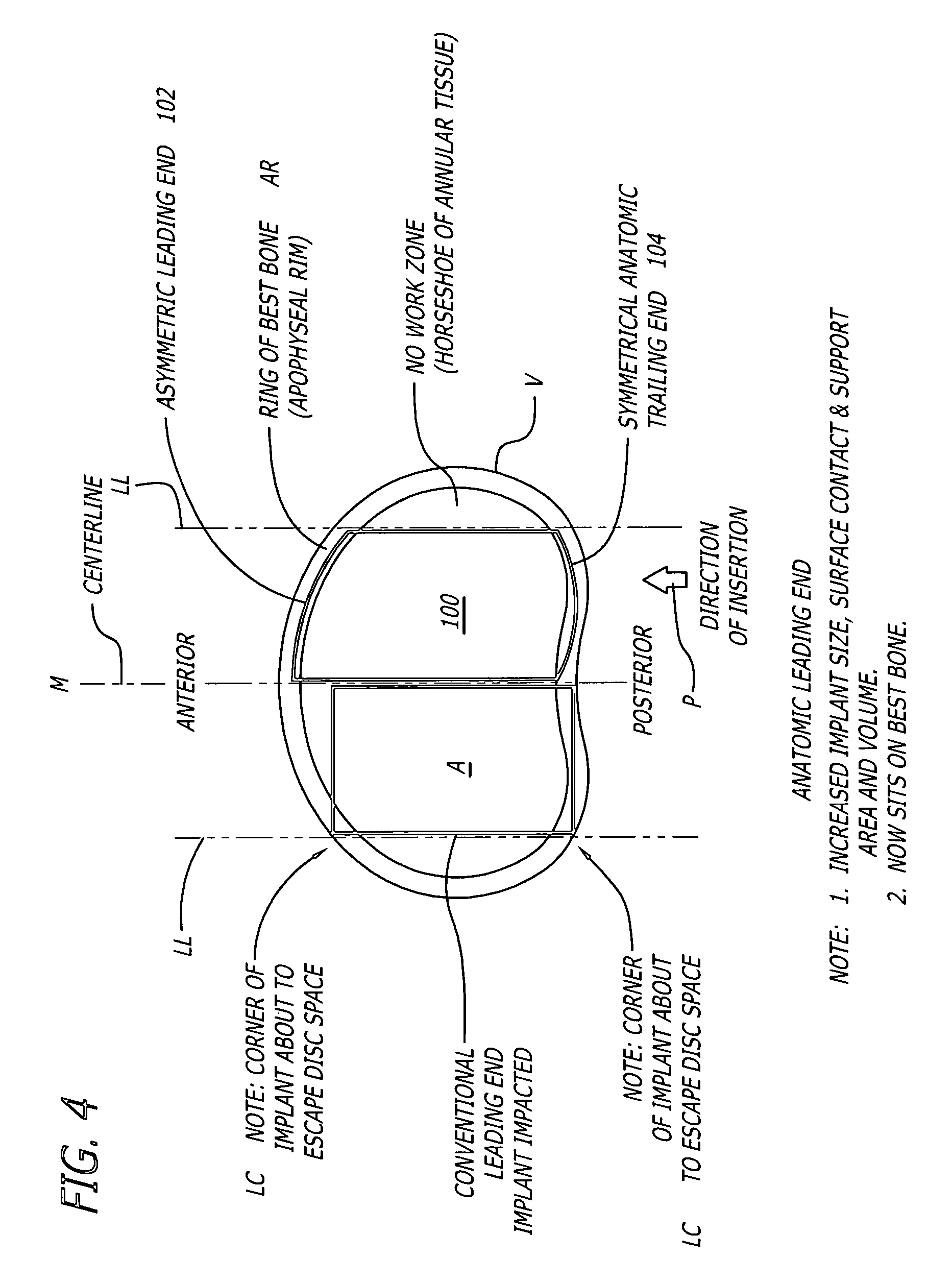
[0045]FIG. 4 shows an embodiment of the present invention comprising an interbody spinal implant generally referred by the numeral 100, inserted in the direction of arrow P from the posterior aspect of a vertebral body V on one side of the centerline M in the lumbar spine. Implant 100 has a leading end 102 for insertion into the disc space and an opposite trailing end 104. In a preferred embodiment, leading end 102 is configured to not extend beyond the outer dimensions of the two vertebral bodies adjacent the disc space proximate leading end 102 after implant 100 is installed, to maximize the area of contact of the implant with the vertebral bone. Leading end 102 could be described as being generally configured to generally conform to at least a portion of the natural anatomical curvature of the aspect of the vertebral bodies adjacent the disc space proximate leading end 102 after implant 100 is installed. The general configuration of leading end 102 is further described in connect...


PUM

PropertyMeasurementUnit
Lengthaaaaaaaaaa
Widthaaaaaaaaaa
Distanceaaaaaaaaaa

Abstract

An artificial interbody spinal implant adapted for placement across an intervertebral space formed across the height of a disc space between two adjacent vertebral bodies is disclosed. The implant has an asymmetrical leading end adapted to sit upon the more peripheral areas, such as the apophyseal rim and the apophyseal rim area, of the vertebral end plate region of the vertebral bodies without protruding therefrom. The asymmetrical leading end allows for the safe use of an implant of maximum length for the implantation space into which it is installed. The implant can also include an asymmetric trailing end adapted to sit upon the more peripheral areas of the vertebral end plate region of the vertebral bodies.

Description

[0001]This application is a divisional of application Ser. No. 09 / 553,573, filed Apr. 19, 2000, the disclosure of which is incorporated herein by reference.BACKGROUND OF THE INVENTION[0002]1. Field of the Invention[0003]The present invention relates generally to interbody spinal implants preferably adapted for placement in pairs side by side to either side of the midline with or without a space therebetween into a space created across the height of a disc space and between two adjacent vertebral bodies, after the removal of damaged spinal disc material, for the purpose of correcting spinal disease at that interspace. The spinal implants are made of an implant material that is other than bone and may or may not be resorbable. Where the implants are spinal fusion implants, they are adapted such that fusion occurs at least in part through the implants themselves. Where the implants are motion preserving for maintaining spinal motion, bone growth can occur at least in part into the spin...

Claims


Application Information

Patent Timeline
IPC IPC(8): A61F2/44A61F2/00A61F2/02A61F2/28A61F2/30
CPCA61F2/4455A61F2/446A61F2/28A61F2310/00179A61F2002/2817A61F2002/30062A61F2002/30777A61F2002/30785A61F2002/30904A61F2002/4475A61F2002/448A61F2210/0004A61F2310/00023A61F2310/00029A61F2310/00131A61F2/442A61F2002/30593
Inventor MICHELSON, GARY K.
Owner WARSAW ORTHOPEDIC INC
Why Eureka
Try Eureka