Vibration detection device and vibration correcting optical device

a technology of optical devices and vibration detection, which is applied in the field of vibration detection devices and optical devices for correcting vibration, can solve the problems of unsteady handling by users, unfavorable use of cameras, and unsteady handling of optical devices such as binoculars and photographing equipment such as cameras, and achieve the effect of accurately and efficiently detecting vibrations

Inactive Publication Date: 2007-01-16
NIKON CORP
View PDF13 Cites 14 Cited by
  • Summary
  • Abstract
  • Description
  • Claims
  • Application Information

AI Technical Summary

Benefits of technology

[0032]The present invention, therefore, provides a vibration detection device that is capable of detecting vibrations a...

Problems solved by technology

A primary cause of vibrations to which optical devices such as binoculars and photographing apparatuses such as cameras are subjected is unsteady handling by the user.
However, the camera may not always be used in a stationary state.
However, these vibration correcting optical devices in the related art do not always operate as intended by the photographer.
For instance, a relatively large vibration occurring while the photographer is aboard a vehicle sometimes causes an erroneous judgment that the photographer is performing a panning photographing operation.
However, the following problems arise when a vibration correcting optical device assumes such switch settings.
However, sin...

Method used


Image

  • Vibration detection device and vibration correcting optical device
  • Vibration detection device and vibration correcting optical device
  • Vibration detection device and vibration correcting optical device

Examples


first embodiment -

-First Embodiment-

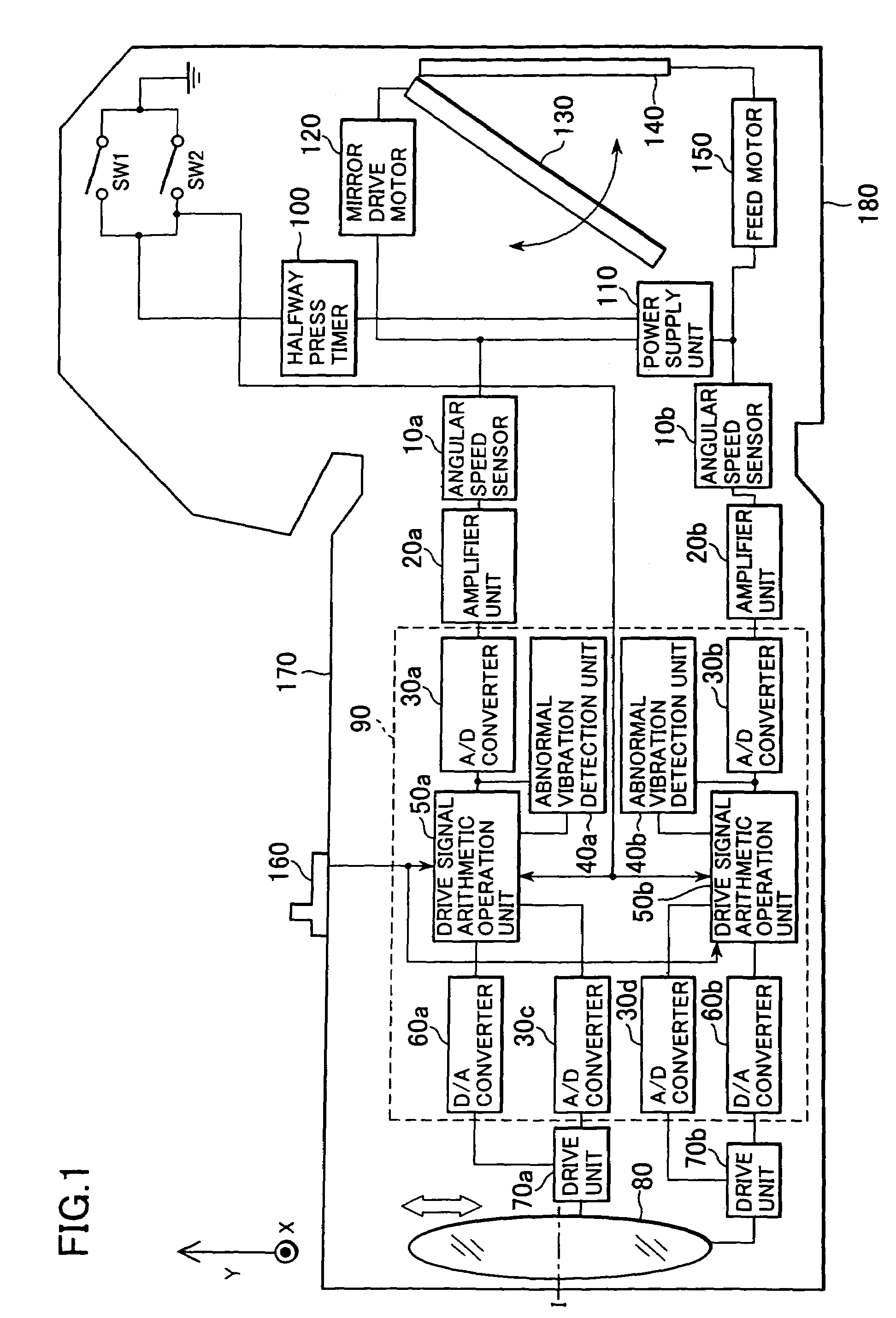
[0056]The following is an explanation of the first embodiment of the present invention, given in reference to the drawings. FIG. 1 is a block diagram schematically illustrating the vibration detection device and the vibration correcting optical device (optical apparatus) according to the first embodiment of the present invention. In this embodiment, the present invention is adopted in a vibration correcting camera which uses silver halide film.

[0057](Outline of a Vibration Correcting Camera)

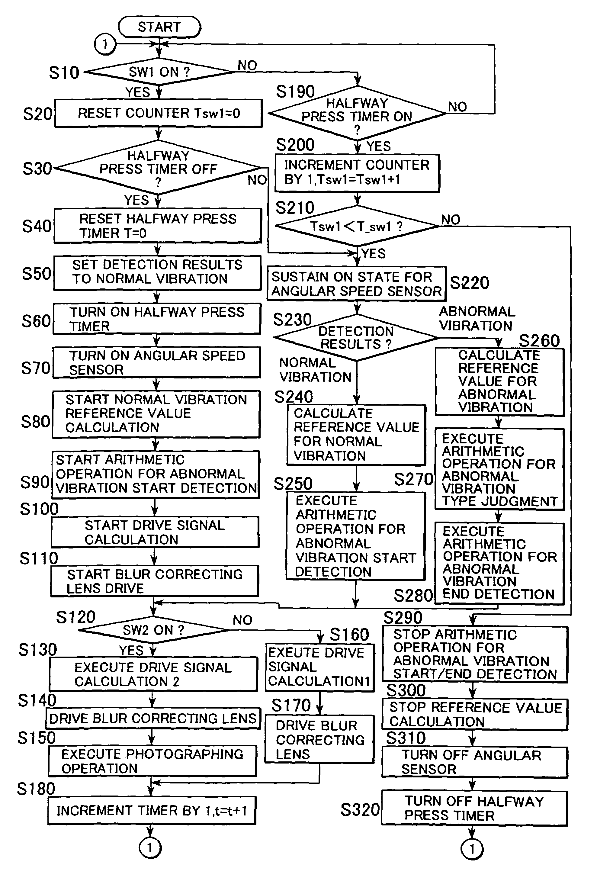
[0058]A halfway press switch SW 1 enters an on state by interlocking with a halfway press operation of a shutter release button (not shown). As this halfway press switch SW 1 is turned on, a series of photographic preparatory operations including a photometric calculation executed by a photometering unit (not shown) and autofocus drive by an autofocus drive unit (not shown) is started. In addition, if a halfway press timer 100 has been in an off state, the halfway press timer 10...

second embodiment -

-Second Embodiment-

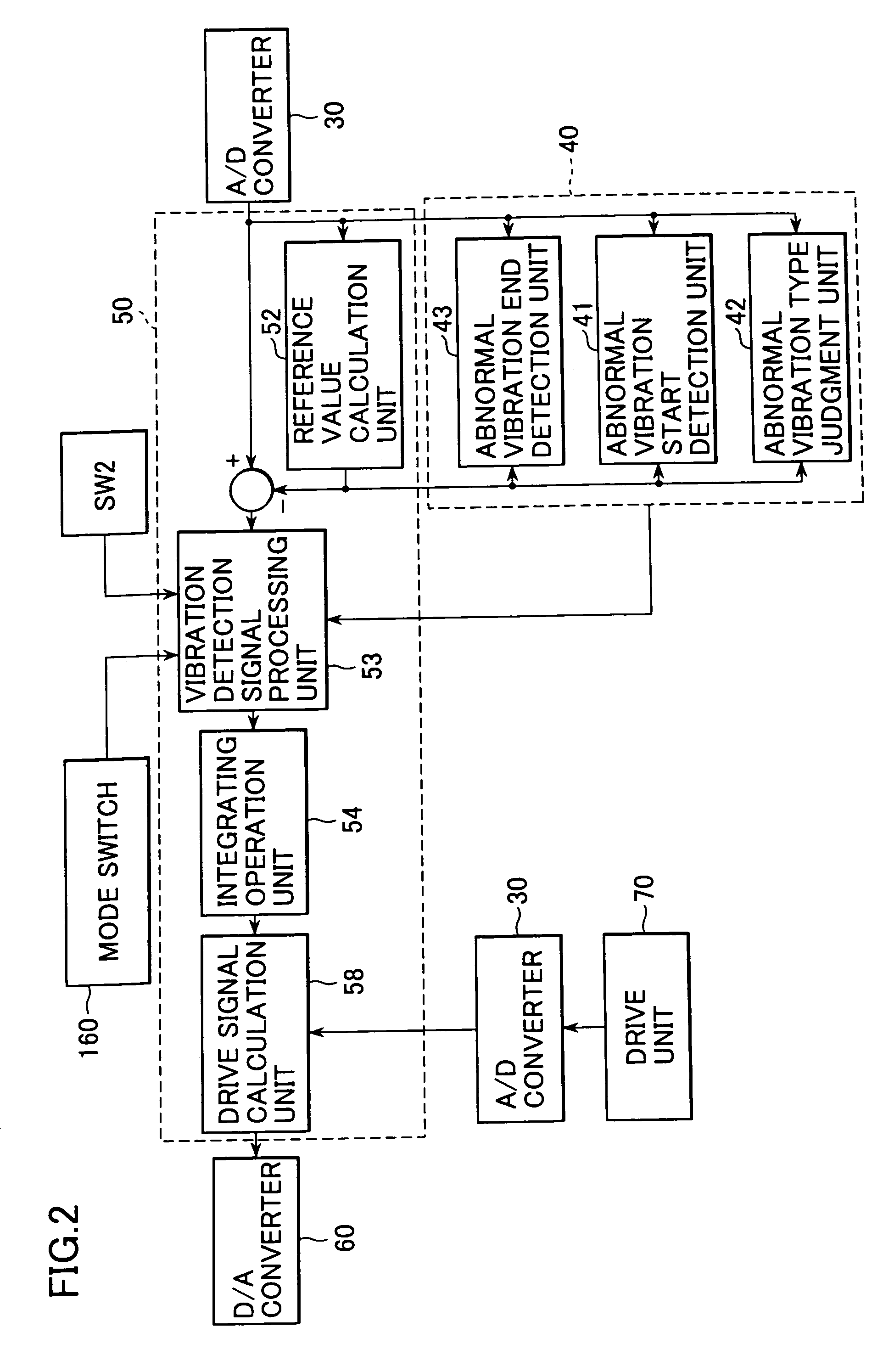
[0205]In the first embodiment, the mode switch 160 is provided to allow the photographer to choose the vibration correcting operation mode in conformance to the specific purpose for which the camera is being used (the photographing conditions). Accordingly, the drive signal calculation is executed in S130 and S160 in FIG. 3 by taking into consideration the setting at the mode switch 160. By contrast, in the second embodiment, in which the abnormal vibration type judging unit 42 engages in the operation detailed later, the mode switch 160 is not provided. Through the operation of the abnormal vibration type judging unit 42, an accurate and quick detection can be performed efficiently to ascertain whether the photographing operation being performed is a gentle panning photographing operation in which the vibration to which the camera is subjected is constituted of both a movement intended by the photographer and an unintended vibration or the photographing operation...


PUM


Abstract

A vibration correcting optical device includes: a vibration detection unit that detects a vibration of the vibration correcting optical device and outputs a vibration detection signal corresponding to the vibration; a vibration state judgment unit that judges a state of the vibration of the vibration correcting optical device to be one of at least three states, based upon the vibration detection signal; an image vibration correcting optical system that corrects an image vibration caused by the vibration of the vibration correcting optical device; a drive unit that drives the image vibration correcting optical system based upon a drive signal; a drive signal arithmetic operation unit that calculates the drive signal based upon the vibration detection signal and outputs the drive signal to the drive unit; and a drive signal calculation control unit that controls a method for calculating the drive signal adopted at the drive signal arithmetic operation unit in conformance to the state of the vibration ascertained through a judgment executed by the vibration state judgment unit.

Description

[0001]This is a Continuation of Application Ser. No. 10 / 347,689 filed Jan. 22, 2003 now U.S. Pat. No. 6,778,766. The entire disclosure of the prior application is hereby incorporated by reference herein in its entirety.INCORPORATION BY REFERENCE[0002]The disclosures of the following priority applications and Laid-open patent publications are herein incorporated by reference:[0003]Japanese Patent Application No. 2002-016971 filed Jan. 25, 2002[0004]Japanese Patent Application No. 2002-040223, filed Feb. 18, 2002[0005]Japanese Laid-open Patent Publication No. H 05-142614[0006]Japanese Laid-open Patent Publication No. H 07-261234[0007]Japanese Laid-open Patent Publication No. H 10-213832[0008]Japanese Laid-open Patent Publication No. 2000-039640BACKGROUND OF THE INVENTION[0009]1. Field of the Invention[0010]The present invention relates to a vibration detection device that detects a vibration caused by a hand movement or the like and a vibration correcting optical device internally pro...

Claims


Application Information

Patent Timeline
IPC IPC(8): G03B17/00
CPCG03B17/00
Inventor TOMITA, HIROYUKI
Owner NIKON CORP
Why Eureka
Try Eureka