
Electric power steering apparatus and electricity supply system

a technology of electric power steering and electricity supply system, which is applied in the direction of electrical steering, dynamo-electric converter control, transportation and packaging, etc., can solve the problems of increasing manufacturing costs, inability to determine whether there is an abnormality in a high-voltage battery or a dc/dc converter, and inability to extend the total length of lines, etc., to achieve stably supplying driving electricity and simple configuration

Active Publication Date: 2006-04-27
JTEKT CORP
View PDF6 Cites 5 Cited by
  • Summary
  • Abstract
  • Description
  • Claims
  • Application Information

AI Technical Summary

Benefits of technology

[0009] Accordingly, it is an objective of the present invention to provide an electric power steering apparatus and an electricity supply system that have simple configuration and are capable of stably supplying driving electricity even if the input of checking signals indicating the state of a vehicle power supply is disrupted due to a failure in an in-vehicle network.

Problems solved by technology

However, in a vehicle where various types of actuators are controlled based on mutual communication through an in-vehicle network, a failure in the in-vehicle network can disrupt the input of various types of signals required for various types of control.
When the input of the signal is disrupted, the EPSECU cannot determine whether there is an abnormality in a high-voltage battery or the DC / DC converter.
However, if a complete redundancy of control lines is established by making control lines forming the in-vehicle network redundant as in the above configuration of the bypass lines, the extended total length of the lines increases the manufacturing costs.
Also, to avoid the complexity of wiring due to redundant control lines, the wiring layout of control lines needs to be newly designed, which further increases the costs.

Method used


Image

  • Electric power steering apparatus and electricity supply system
  • Electric power steering apparatus and electricity supply system
  • Electric power steering apparatus and electricity supply system

Examples


Embodiment Construction

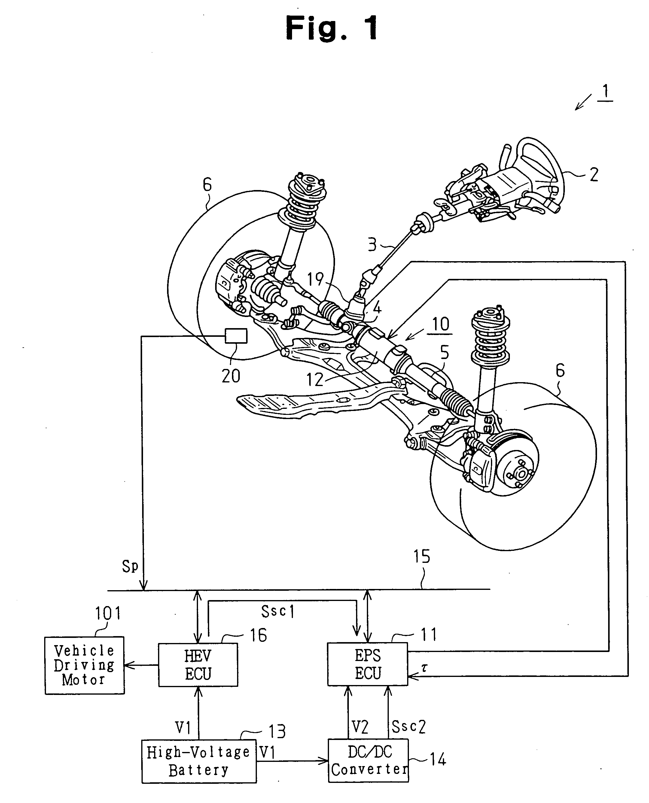
[0018] Hereinafter, an electric power steering apparatus (EPS) for a high-voltage vehicle according to a preferred embodiment of the present invention will be described with reference to the drawings.

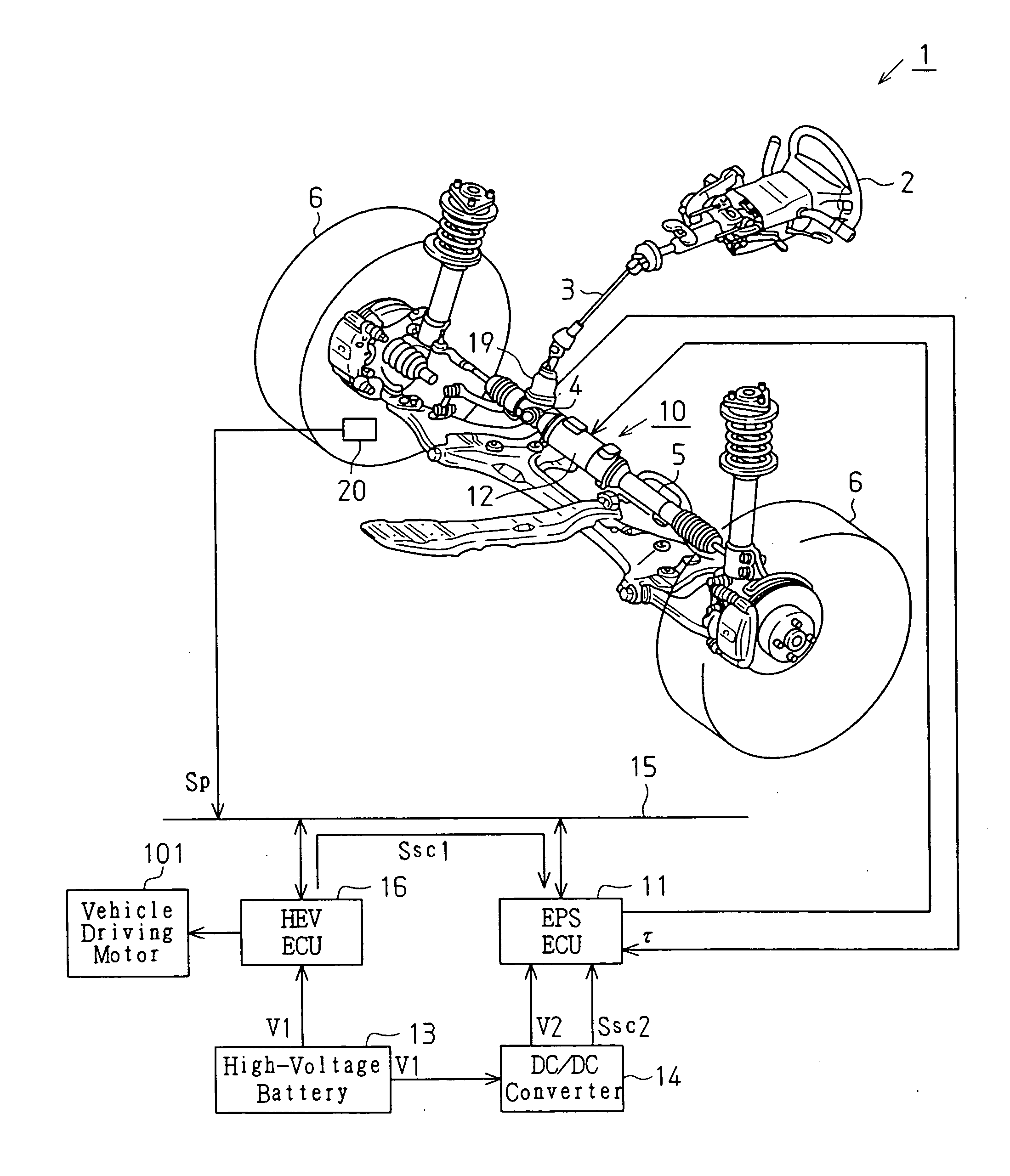
[0019]FIG. 1 is a schematic view illustrating an EPS 1 according to the present embodiment. As shown in FIG. 1, a steering shaft 3 extending from a steering wheel 2 is coupled to a rack 5 with a rack-and-pinion mechanism 4. Rotation of the steering shaft 3 accompanying a steering operation of the steering wheel 2 is converted into linear reciprocation of the rack 5 by means of the rack-and-pinion mechanism 4. According to the linear reciprocation of the rack 5, the angle of steered wheels 6, that is, the steered wheel angle, is changed. This in turn changes the traveling direction of the vehicle. The steering wheel 2, the steering shaft 3, the rack-and-pinion mechanism 4, and the rack 5 form a steering system of the vehicle.

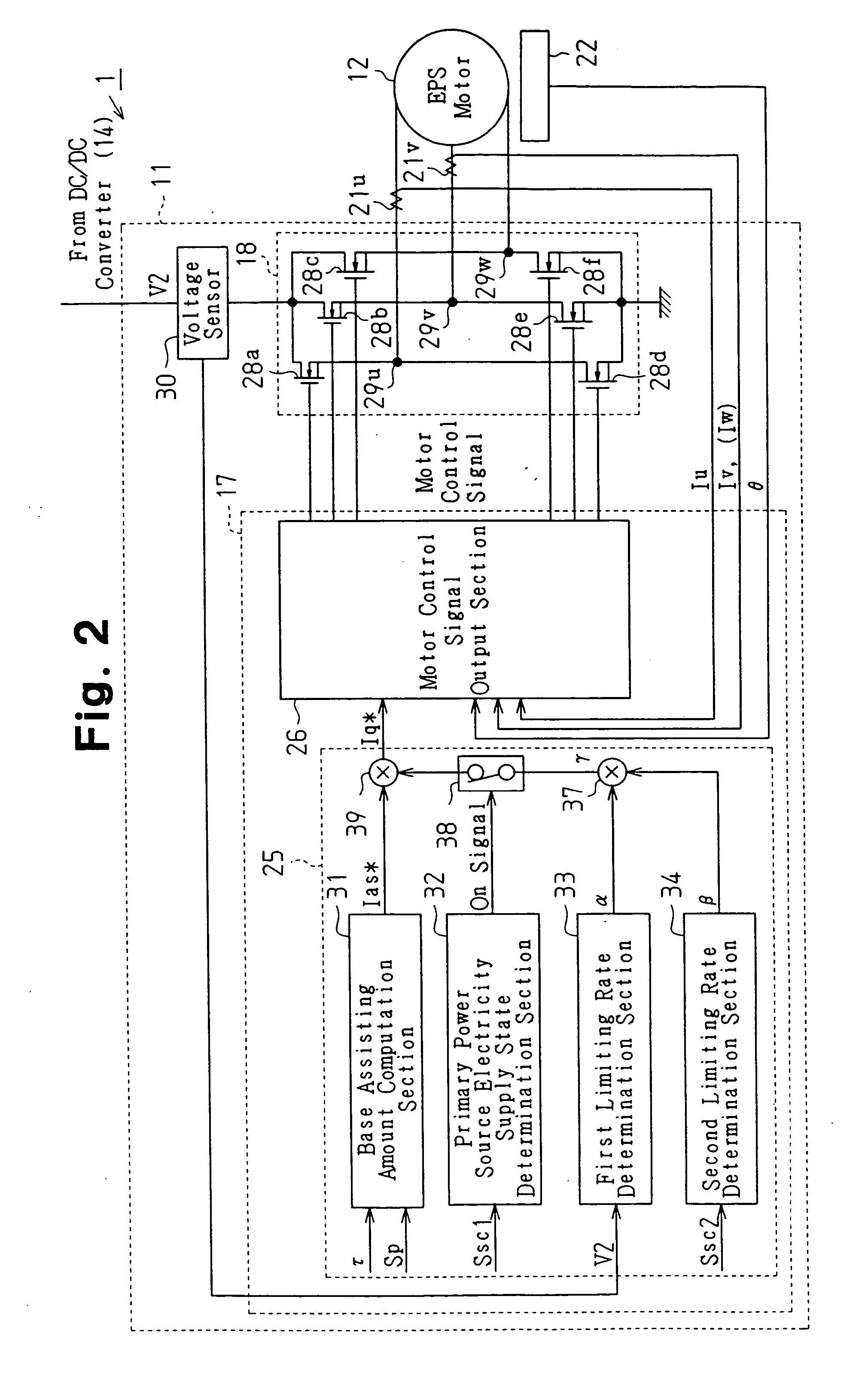
[0020] The EPS 1 includes an EPS actuator 10 and an EPSECU 11...


PUM


Abstract

A transformer section transforms a primary voltage and outputs secondary voltage. A control section inputs a first signal indicating a state of electricity supply of a primary power source through an in-vehicle network. The transformer section outputs a second signal indicating a state of electricity supply of the transformer section. When the input of the first signal is disrupted, the control section limits the driving electricity supplied to the steering motor based on at least one of a value of the secondary voltage and the electricity supply state of the transformer section indicated by the second signal. Accordingly, driving electricity is stably supplied with the steering motor with a simple configuration even if the input of the first signal is disrupted due to a failure in the in-vehicle network.

Description

CROSS-REFERENCE TO RELATED APPLICATIONS [0001] This application is based upon and claims the benefit of priority from prior Japanese Patent Application No. 2004-308159, filed on Oct. 22, 2004, the entire contents of which are incorporated herein by reference. BACKGROUND OF THE INVENTION [0002] The present invention relates to an electric power steering apparatus and an electricity supply system. [0003] In recent years, various types of electric components and electronic control systems for vehicles have been introduced. In-vehicle networks for connecting a plurality of control devices with control lines, such as a controller area network (CAN) have been applied to an increased number of cars. This prevents the wiring from being complicated and allows control devices of various types of actuators to communicate with each other and share information. Also, the CAN permits the control devices to be integrally controlled. [0004] Electric cars, fuel cell cars, and hybrid cars that switch...

Claims


Application Information

Patent Timeline
Patent Type & Authority Applications(United States)
IPC IPC(8): H02P7/00B62D5/04B62D6/00B62D119/00B62D137/00
CPCB62D5/046Y02T10/7258Y02T10/72
Inventor IWAZAWA, MASAHIDE
Owner JTEKT CORP
Learn More