Signal-processing method, signal-processing system, and semiconductor device configured to detect physical-quantity distribution

a signal processing and physical-quantity distribution technology, applied in the field of signal processing systems and semiconductor devices, can solve the problems of increasing the cost of making the system, increasing the power consumption of the dsp, increasing the size of the gate, the chip size, etc., and achieving the effect of simple configuration, increased camera system performance, and increased chip siz

Inactive Publication Date: 2012-04-17
SONY CORP
View PDF17 Cites 6 Cited by
  • Summary
  • Abstract
  • Description
  • Claims
  • Application Information

AI Technical Summary

Benefits of technology

[0032]Therefore, in the above-described configuration, the gate size, chip size, and power consumption of the DSP are increased, which makes it difficult to add a new function or increase the performance of the camera system including the image-pickup element and the DSP by using a simple configuration at low cost. Subsequently, it is difficult to provide a digital still camera or a mobile phone with a camera that is low priced and capable of functioning with stability.
[0033]Accordingly, the present invention is adapted to present a system that can perform highly sophisticated signal processing without making the configuration of a semiconductor such as an image-pickup element complicated and increasing the cost of forming the system.

Problems solved by technology

However, known control-and-signal-processing configurations are insufficient to respond to such a demand without using a complicated configuration and increasing the cost of making the system.
Therefore, in the above-described configuration, the gate size, chip size, and power consumption of the DSP are increased, which makes it difficult to add a new function or increase the performance of the camera system including the image-pickup element and the DSP by using a simple configuration at low cost.
Subsequently, it is difficult to provide a digital still camera or a mobile phone with a camera that is low priced and capable of functioning with stability.

Method used


Image

  • Signal-processing method, signal-processing system, and semiconductor device configured to detect physical-quantity distribution
  • Signal-processing method, signal-processing system, and semiconductor device configured to detect physical-quantity distribution
  • Signal-processing method, signal-processing system, and semiconductor device configured to detect physical-quantity distribution

Examples


first embodiment

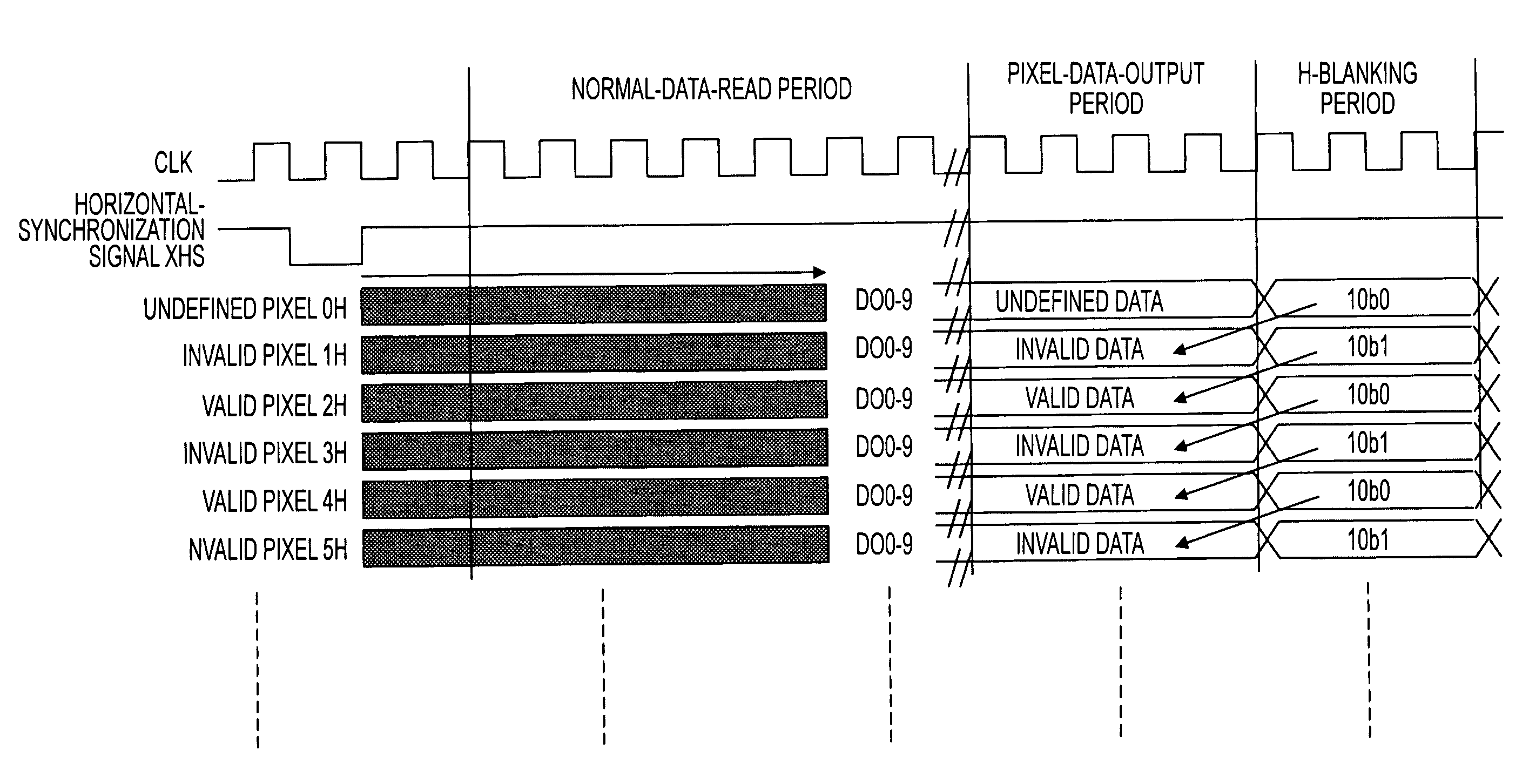
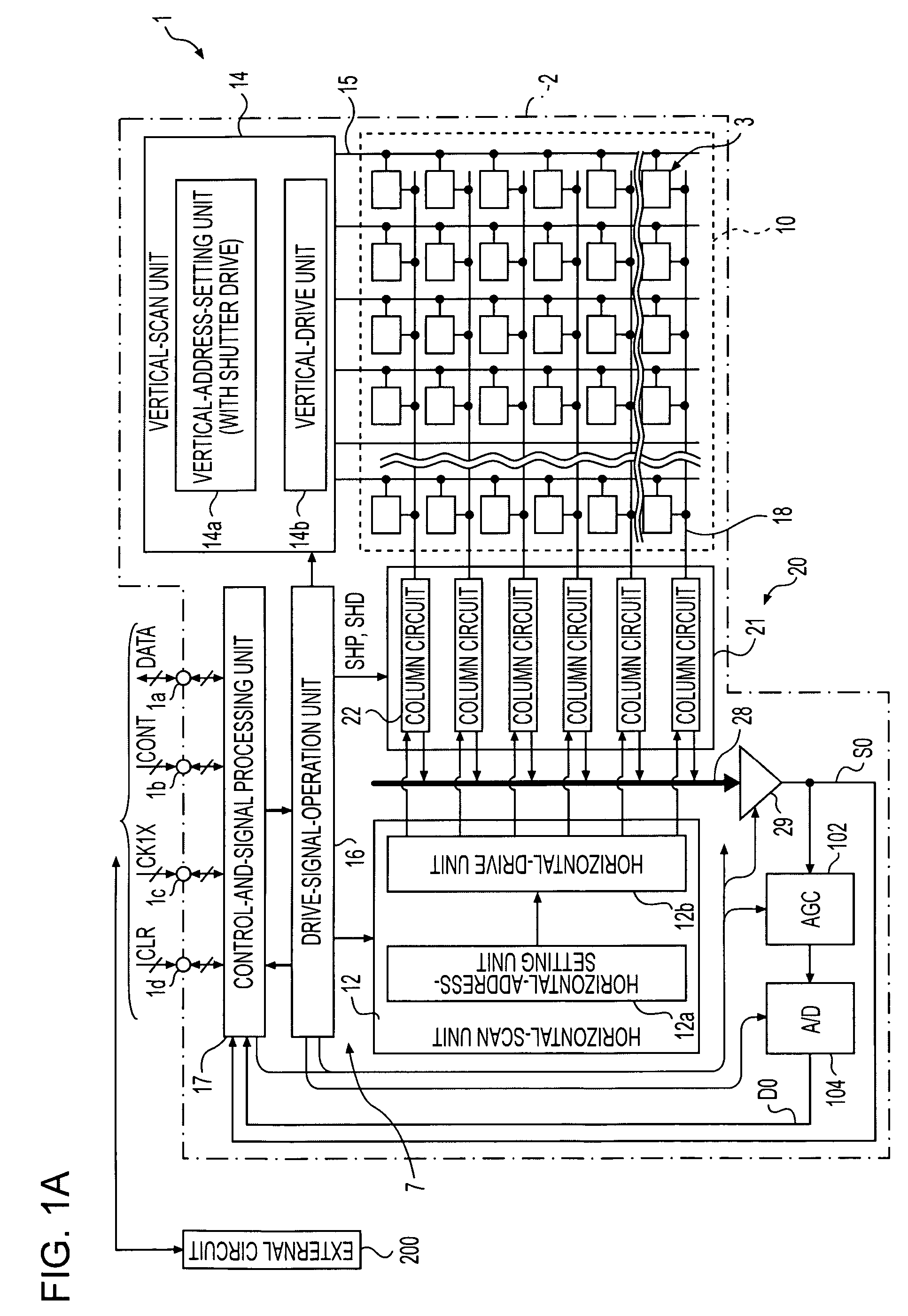
[0101]The example operations will be described, as below. Under normal conditions, the image-pickup device 1 externally transmits image data alone by using the digital-output terminal 1a from which the image data D0 is transmitted. However, where the image-pickup device 1 is set to a special mode, the image-pickup device 1 transmits a signal indicating the meaning of data externally transmitted at the time where the next line is accessed to the external circuit 200, as a signal for confirming the internal operation of the solid-state image-pickup element 2, separately from the image data D0, in a horizontal-blanking period in a single horizontal period specified by a horizontal-synchronization signal XHS. Subsequently, the external circuit 200 refers to the internal-operation information corresponding to the signal indicating the meaning of data externally transmitted at the time where the next line is accessed and performs the zoom function, where the details on signal processing ...

second embodiment

[0135]FIG. 7 is a timing chart illustrating operations of the present invention, where the operations are performed by the image-pickup device 1 shown in FIG. 1. FIG. 7 shows an example technology for achieving a dynamic-range-enlargement function.

[0136]In the past, gain adjustment in frames is performed in the solid-state image-pickup element 2 and / or the external circuit 200, so as to achieve the dynamic-range-enlargement function. However, according to the second embodiment, gain adjustment is performed in lines by the solid-state image-pickup element 2. That is to say, where the dynamic-range-enlargement function of the second embodiment is performed, the details on the gain adjustment vary from line to line. The solid-state image-pickup element 2 transmits gain-setting information about each of the lines to the external circuit 200. Then, the external circuit 200 performs correction processing by referring to the transmitted gain-setting information, whereby an image with a wid...

third embodiment

[0139]FIG. 8 is a timing chart illustrating operations according to the present invention, where the operations are performed by the image-pickup device 1 shown in FIG. 1. FIG. 8 shows the example where address information about an accessed line H and / or address information related to the line H is transmitted to the external circuit 200.

[0140]According to the details on signal processing performed by the external circuit 200, not only information about the pixels corresponding to the line currently accessed, but also information about a pixel preceding the current line by as much as several pixels is often required. For example, the preceding-pixel information is required, where signal processing is performed for at least two lines by using several lines of data. The signal processing includes the color processing, the black-level adjustment, and so forth.

[0141]Therefore, according to the operations of the third embodiment, the preceding-pixel information is transmitted to the exte...


PUM


Abstract

A signal-processing method adapted to perform predetermined signal processing based on a unit signal transmitted from a semiconductor device that includes at least two unit components arranged in a predetermined order, where each of the unit components includes a detection unit configured to detect change information responsive to a change in an incident physical quantity and a unit-signal-generation unit configured to generate the unit signal based on the change information, and that detects the distribution of the physical quantity is provided. The signal-processing method includes the steps of externally transmitting operation information that can specify an operation state of the semiconductor device from the semiconductor device and performing the predetermined signal processing based on the unit signal by referring to the operation information in a signal-processing unit provided outside the semiconductor device.

Description

CROSS REFERENCES TO RELATED APPLICATIONS[0001]The present invention contains subject matter related to Japanese Patent Application JP 2004-320265 filed in the Japanese Patent Office on Nov. 4, 2004, the entire contents of which are incorporated herein by reference.BACKGROUND OF THE INVENTION[0002]1. Field of the Invention[0003]The present invention relates to a signal-processing method, a signal-processing system, and a semiconductor device configured to detect the physical-quantity distribution (hereinafter often referred to as a physical-information-acquisition device). More specifically, the present invention relates to a signal-processing technology adapted to acquire information used for a predetermined object by reading a signal. The signal-processing technology is useful for a semiconductor device configured to detect the physical-amount distribution. The semiconductor device includes, for example, a solid-state image-pickup device that includes at least two unit components a...

Claims


Application Information

Patent Timeline
Patent Type & Authority Patents(United States)
IPC IPC(8): H04N5/262H04N5/335H04N5/341H04N5/355H04N5/367H04N5/372H04N5/374H04N5/376
CPCH04N5/3454H04N5/3658H04N5/367H04N5/376H04N25/443H04N25/677H04N25/68H04N25/74
Inventor MATSUMOTO, KENHISAMATSU, YASUAKIIZUMI, DAISAKUSATO, FUMINORIITOH, MASAHIROSAIKAWA, RYOUKO
Owner SONY CORP
Why Eureka
Try Eureka