Power conversion system and method of converting power

a power conversion system and power conversion technology, applied in the direction of dc-ac conversion without reversal, dc source parallel operation, transportation and packaging, etc., can solve the problems of system cost and efficiency not being optimised, and achieve the effect of reducing the aggregate power rating of the converter, high overall efficiency and power factor

Inactive Publication Date: 2006-07-04
CURTAIN UNIV OF TECH
View PDF11 Cites 288 Cited by
  • Summary
  • Abstract
  • Description
  • Claims
  • Application Information

AI Technical Summary

Benefits of technology

[0015]It is an object of the present invention to provide a power conversion system having a plurality of converters with reduced aggregate power rating of the converters while still providing all power flow requirements, maintaining high overall efficiency and power factor.

Problems solved by technology

Energy not intended for the battery 14 must then be converted again, resulting in a system where the cost and efficiency has not been optimised.

Method used


Image

  • Power conversion system and method of converting power
  • Power conversion system and method of converting power
  • Power conversion system and method of converting power

Examples


Embodiment Construction

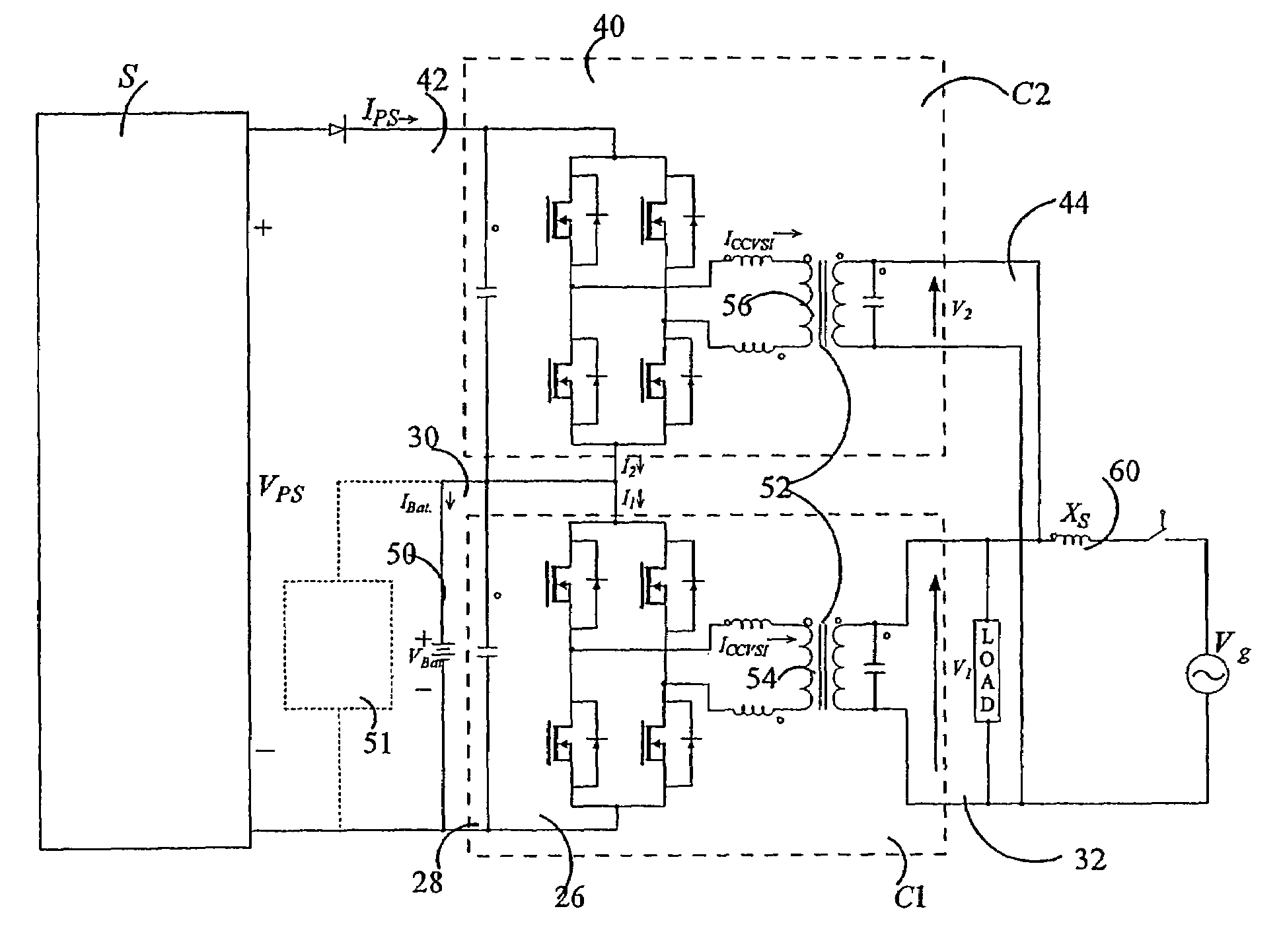
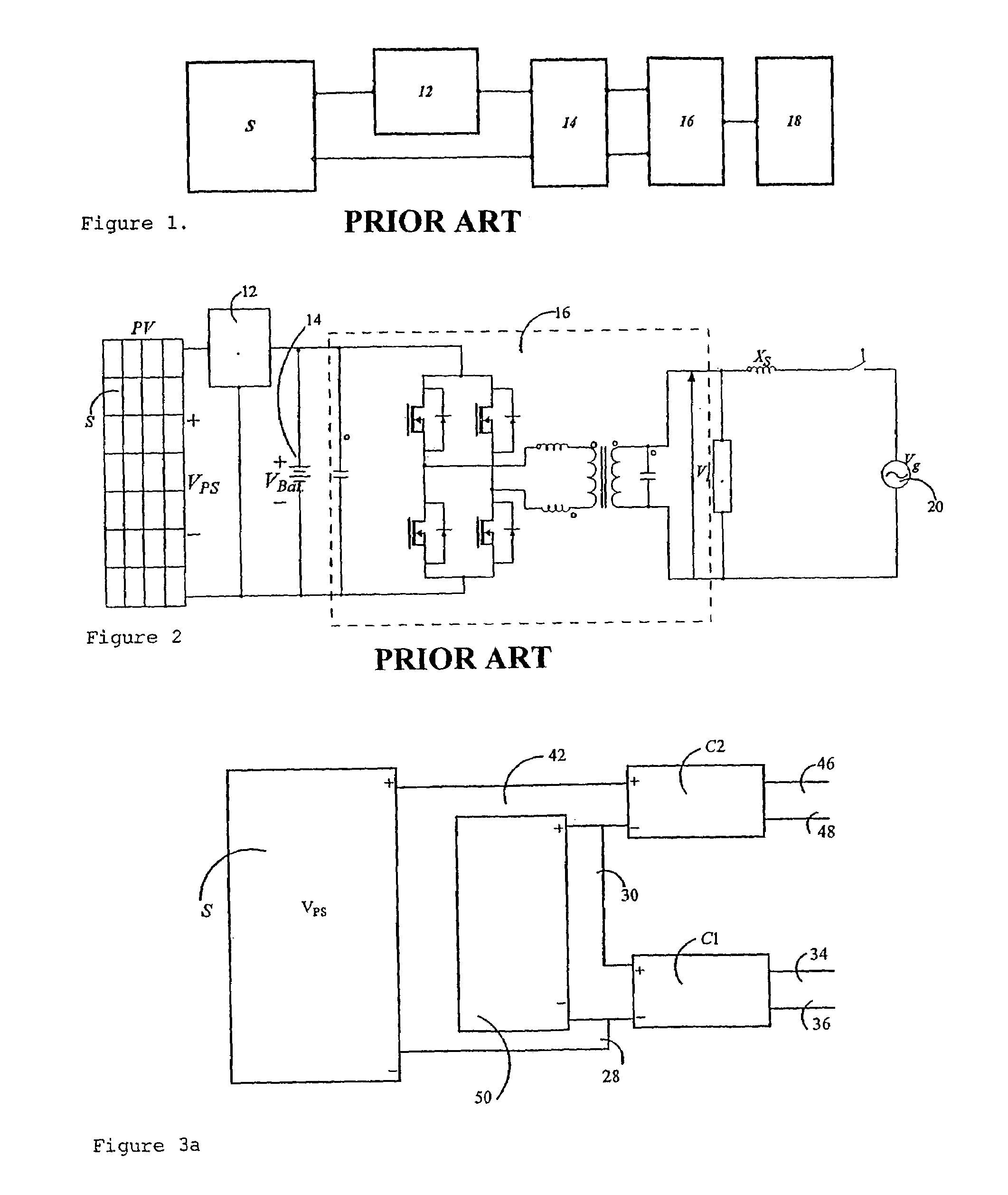
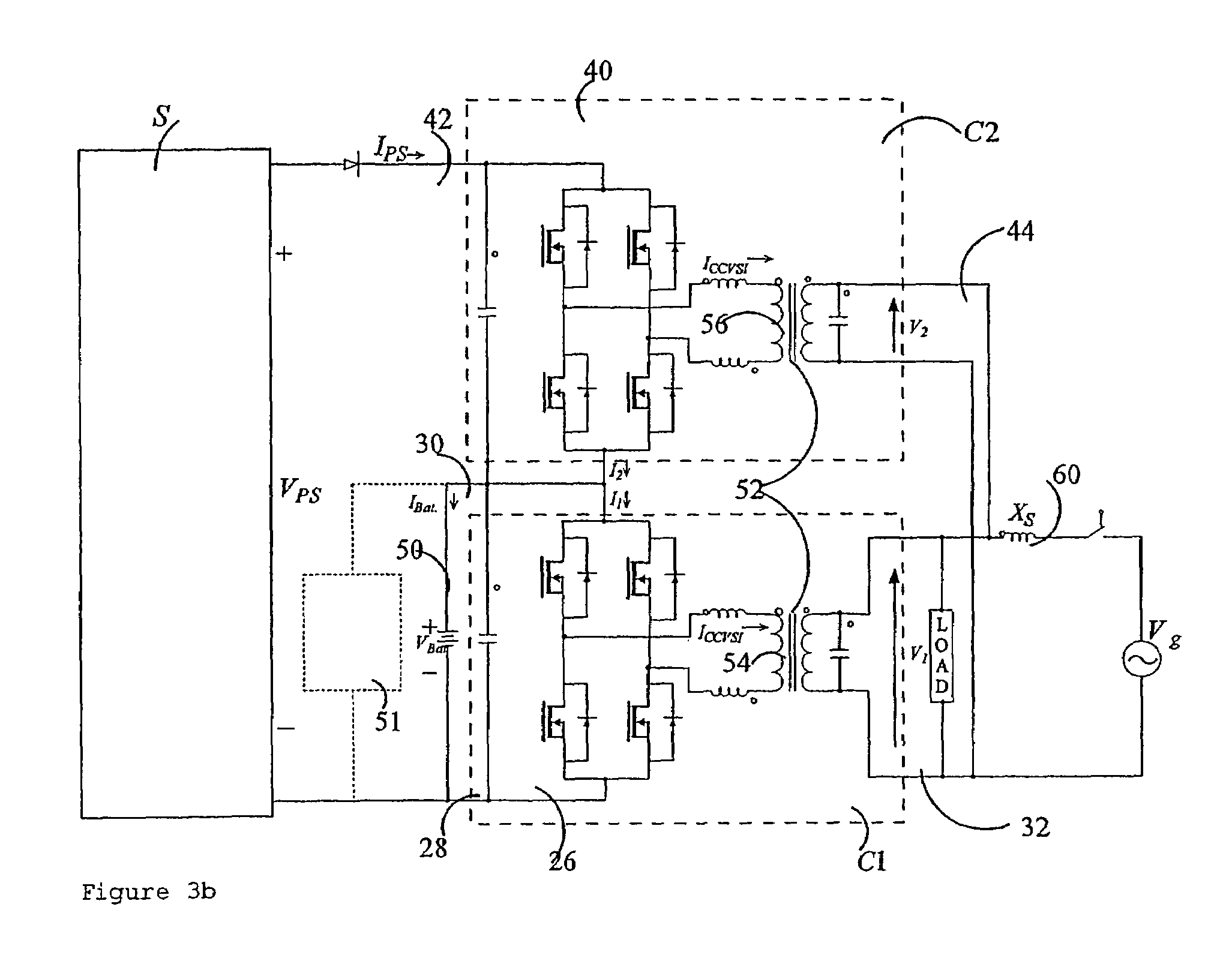
[0079]Referring in particular to FIGS. 3a, 3b and 3c, a single phase power conversion system 22 in accordance with the present invention includes a first converter C1 having a DC side 26 manifested by lines 28 and 30 and an AC side 32 manifested by lines 34 and 36; and a second converter C2 having an DC side 40 manifested by lines 30 and 42 and an AC side 44 manifested by lines 46 and 48. The system 22 further includes an electrical energy storage device in the form of a battery 50. It should be noted that the power conversion system can be realised as a multiphase, and in particular a three phase, system. The following description of a single phase system can also be taken as a description of one phase in a multiphase system.

[0080]In each of these embodiments, both of the converters C1 and C2 are bi directional although in an alternate embodiment, the converter C2 may be in the form of an inverter providing power conversion from DC to AC only. Of course this may also be manifested ...


PUM


Abstract

A power conversion system includes a first converter having a DC side and an AC side and a second converter having a DC side and an AC side. The DC sides of the converters are connected in series with a battery connected in parallel across the DC side of the first converter. The AC sides of the converters are connected in parallel across an AC voltage grid. A DC generating power source is coupled across the DC sides of both converters. The first converter is bi-directional with the second converter being either an inverter providing DC to AC conversion or alternately a bi-directional inverter.

Description

CROSS REFERENCE TO RELATED APPLICATIONS[0001]This application is a continuation of PCT / AU03 / 00382, filed Mar. 28, 2003, and titled “Power Conversion System and Method of Converting Power,” which claims priority under 35 U.S.C. §119 to Australian Application No. PS 1439, filed on Mar. 28, 2002, and titled “Power Conversion System and Method of Converting Power,” the entire contents of which are hereby incorporated by reference.FIELD OF THE INVENTION[0002]The present invention relates to a power conversion system particularly, though not exclusively, adapted to provide continuous power to single or multiple phase AC loads when fed from separate DC and single or multiple phase AC sources. The invention further relates to a method of converting power.BACKGROUND OF THE INVENTION[0003]Many “Alternative” Energy Sources (AES), such as photovoltaic (PV) modules, produce maximum power at a DC output voltage that varies widely depending upon the solar insolation levels, ambient temperature and...

Claims


Application Information

Patent Timeline
Patent Type & Authority Patents(United States)
IPC IPC(8): H02M7/00H02J7/00H02J3/38H02J7/35H02M7/48H02M7/493
CPCH02J7/35H02M7/493H02J3/383H02J3/386H02J3/385H02M2001/0074H02M2007/4822Y02E10/763Y02E10/563Y02E10/566Y02E10/58H02J2300/28H02J2300/26H02J2300/24H02J3/381Y02E10/56Y02E10/76H02M1/0074H02J3/50
Inventor NAYAR, CHEMMANGOT V.MALENGRET, MICHELBORLE, LAWRENCE J.DEHBONEI, HOOMAN
Owner CURTAIN UNIV OF TECH
Why Eureka
Try Eureka