Motor driving apparatus

a motor and motor technology, applied in the direction of electronic commutators, domestic cooling devices, dynamo-electric converter control, etc., can solve the problems of reduced motor driving efficiency, excessively large or small weak field current id, and brushless motors cannot be driven at higher rpm, so as to achieve simple and stable weak field control, reduce cost, and high degree of freedom in design

Active Publication Date: 2007-02-13
III HLDG 7
View PDF15 Cites 86 Cited by
  • Summary
  • Abstract
  • Description
  • Claims
  • Application Information

AI Technical Summary

Benefits of technology

[0042]According to a thirteenth aspect of the present invention, there is provided an electric washing machine including a brushless motor for generating power, and a motor driving apparatus for driving the brushless motor, the motor driving apparatus being the motor driving apparatus according to the first aspect. Therefore, it is possible to drive the brushless motor with stability until reaching a high-rpm, by performing simple and stable weak field control for varying only the current advance angle, even under the condition where the input voltage of the inverter varies. Thereby, a washing machine equipped with a brushless motor and a driving apparatus thereof is provided at a reduced cost and with a high degree of freedom in design.
[0043]According to a fourteenth aspect of the present invention, there is provided an air blower including a brushless motor for generating power, and a motor driving apparatus for driving the brushless motor, the motor driving apparatus being the motor driving apparatus according to the first aspect. Therefore, it is possible to drive the brushless motor with stability until reaching a high-rpm, by performing simple and stable weak field control for varying only the current advance angle, even under the condition where the input voltage of the inverter varies. Thereby, an air blower equipped with a brushless motor and a driving apparatus thereof is provided at a reduced cost and with a high degree of freedom in design.
[0044]According to a fifteenth aspect of the present invention, there is provided an electric vacuum cleaner including a brushless motor for generating power, and a motor driving apparatus for driving the brushless motor, the motor driving apparatus being the motor driving apparatus according to the first aspect. Therefore, it is possible to drive the brushless motor with stability until reaching a high-rpm, by performing simple and stable weak field control for varying only the current advance angle, even under the condition where the input voltage of the inverter varies. Thereby, a vacuum cleaner equipped with a brushless motor and a driving apparatus thereof is provided at a reduced cost and with a high degree of freedom in design.
[0045]According to a sixteenth aspect of the present invention, there is provided an electric dryer including a compressor having a brushless motor for generating power, and a motor driving apparatus for driving the brushless motor of the compressor, the motor driving apparatus being the motor driving apparatus according to the first aspect. Therefore, it is possible to drive the brushless motor with stability until reaching a high-rpm, by performing simple and stable weak field control for varying only the current advance angle, even under the condition where the input voltage of the inverter varies. Thereby, a dryer equipped with a brushless motor and a driving apparatus thereof is provided at a reduced cost and with a high degree of freedom in design.
[0046]According to a seventeenth aspect of the present invention, there is provided a heat pump type hot-water supply unit including a compressor having a brushless motor for generating power, and a motor driving apparatus for driving the brushless motor of the compressor, the motor driving apparatus being a motor driving apparatus according to the first aspect. Therefore, it is possible to drive the brushless motor with stability until reaching a high-rpm, by performing simple and stable weak field control for varying only the current advance angle, even under the condition where the input voltage of the inverter varies. Thereby, a hot-water supply unit equipped with a brushless motor and a driving apparatus thereof is provided at a reduced cost and with a high degree of freedom in design.
[0047]According to an eighteenth aspect of the present invention, there is provided a hybrid car including a brushless motor for generating power, and a motor driving apparatus for driving the brushless motor, the motor driving apparatus being the motor driving apparatus according to the first aspect. Therefore, it is possible to drive the brushless motor with stability until reaching a high-rpm, by performing simple and stable weak field control for varying only the current advance angle, even under the condition where the input voltage of the inverter varies. Thereby, a hybrid car equipped with a brushless motor and a driving apparatus thereof is provided at a reduced cost and with a high degree of freedom in design.

Problems solved by technology

As can be seen from formula (5), as the rpm of the brushless motor, i.e., the axial angular velocity ω of the brushless motor, increases, the counter-electromotive voltage ωE increases in proportion to the axial angular velocity ω. Accordingly, if the increase in the counter-electromotive voltage ωE is allowed as it is, the terminal voltage V of the brushless motor becomes higher than the input voltage of the inverter circuit due to the increase in the counter-electromotive voltage ωE, resulting in a problem that the brushless motor cannot be driven at the higher rpm.
However, when controlling the weak field current Id using the table values as described above, the weak field current Id becomes excessively large or small with variations in the input voltage of the inverter circuit.
As a result, the motor driving efficiency is reduced, or the required torque is not satisfied and thereby the maximum rpm cannot be realized.
As is evident from the vector diagram shown in FIG. 11(b) and formula (5), although the terminal voltage is lowered when the weak field current Id flows, a current Id that does not contribute to occurrence of torque is generated, leading to a reduction in efficiency.
Conversely, when the inverter input voltage is low, a weak field current Id that is sufficient to reduce the motor terminal voltage V to no more than the inverter input voltage cannot be supplied, and further, a torque current Iq that is sufficient to obtain a required torque cannot be supplied.
In other words, there is a fear of extremely unstable behavior of the motor depending on the shapes of variations in the input voltage.
Further, since the conventional motor driving apparatus has a circuit for detecting the inverter input voltage, detection accuracy and responsivity in this circuit may adversely affect determination of a weak field current that is a control variable in weak field control.

Method used


Image

  • Motor driving apparatus
  • Motor driving apparatus
  • Motor driving apparatus

Examples


embodiment 1

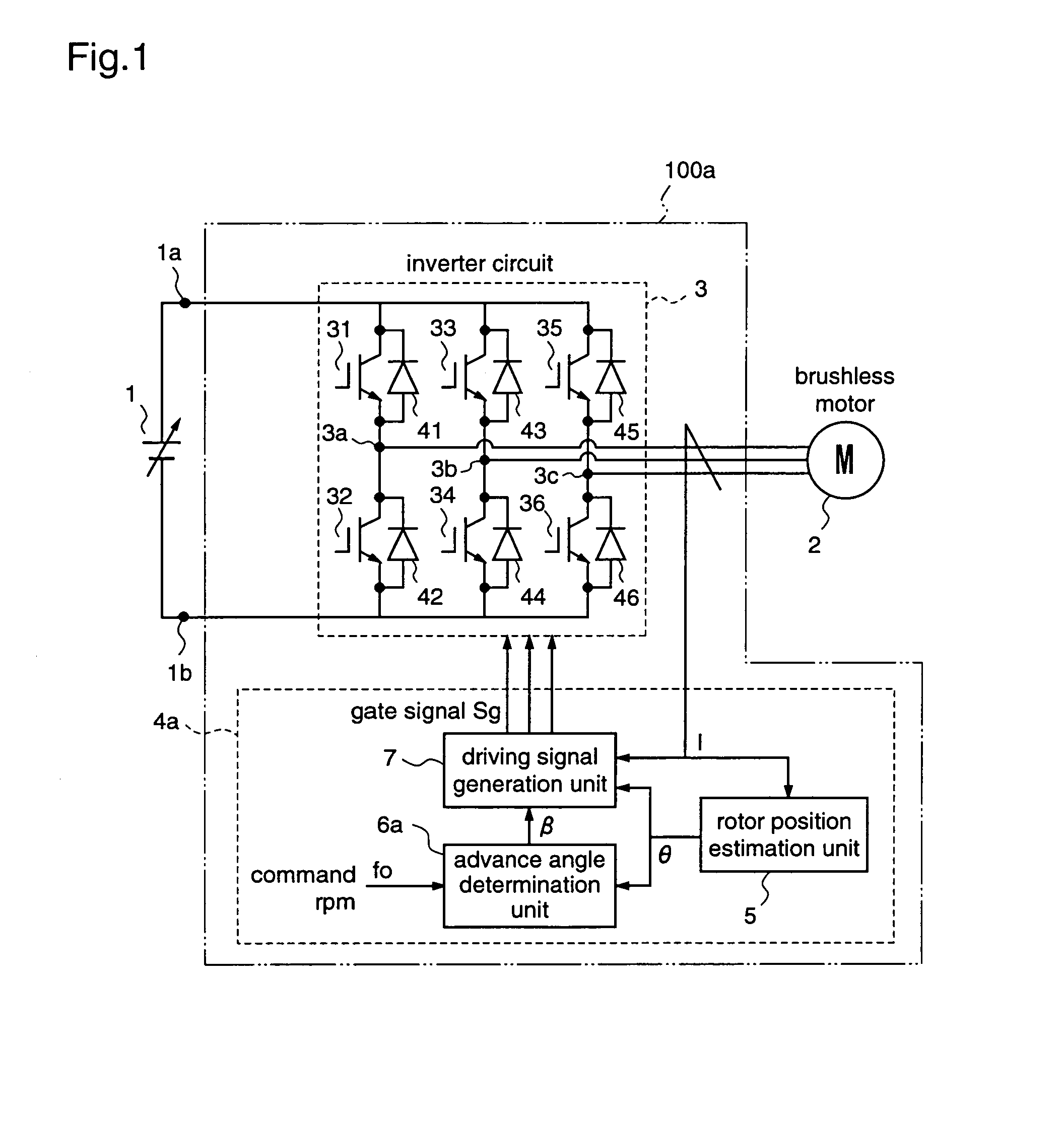
[0072]FIG. 1 is a block diagram for explaining a motor driving apparatus according to a first embodiment of the present invention.

[0073]A motor driving apparatus 100a according to the first embodiment has an input terminal connected to a power supply 1, and drives a brushless motor 2 at a required arbitrary rpm. The motor driving apparatus 100a performs weak field control for the brushless motor 2 by varying an advance angle β of a phase of a motor current with respect to a rotor position of the motor.

[0074]In this first embodiment, the advance angle β of the motor current is controlled so that a deviation between the command rpm to the motor and the actual rpm becomes zero. While in the prior art the control target in the weak field control is the weak field current Id, the advance angle β of the motor current according to the first embodiment and the weak field current Id according to the prior art are similar control targets in the weak field control.

[0075]Hereinafter, an inverte...

embodiment 2

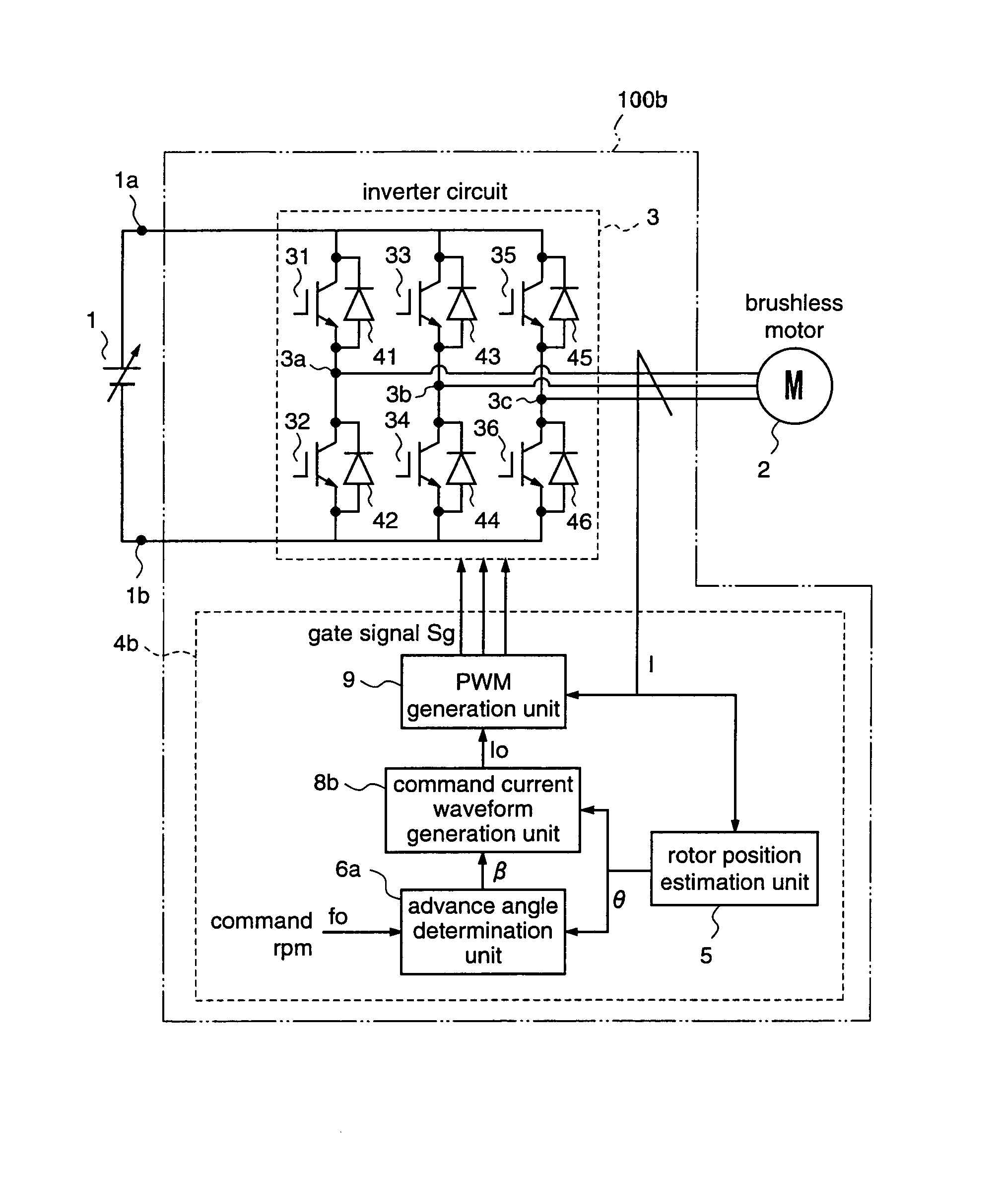
[0111]FIG. 3 is a block diagram for explaining a motor driving apparatus according to a second embodiment of the present invention.

[0112]A motor driving apparatus 100b according to the second embodiment has an input terminal connected to a power supply 1, drives a brushless motor 2 at an arbitrary rpm, and performs weak field control for the brushless motor 2 by adjusting an advance angle β of a motor current, like the motor driving apparatus 100a according to the first embodiment. In this second embodiment, control of the advance angle β of the motor current is carried out so that a deviation between a command rpm fo supplied to the motor and an actual rpm f becomes zero, under the state where the amplitude of the current supplied to the motor is maintained at a constant value.

[0113]To be specific, the motor driving apparatus 100b comprises an inverter circuit 3 for converting an output voltage of the power supply 1 into a three-phase AC and outputting the three-phase AC to the mot...

embodiment 3

[0130]FIG. 5 is a block diagram for explaining a motor driving apparatus according to a third embodiment of the present invention.

[0131]A motor driving apparatus 100c according to the third embodiment has an input connected to the power supply 1, and drives the brushless motor 2 at an arbitrary rpm, like the motor driving apparatus 100b according to the second embodiment. Further, the motor driving apparatus 100c performs weak field control of the brushless motor 2 by adjusting the advance angle β of the motor current so that the actual motor rpm f becomes maximum.

[0132]To be specific, the motor driving apparatus 100c comprises an inverter circuit 3 for converting an output voltage of the power supply 1 into a three-phase AC and outputting the three-phase AC to the motor 2, and an inverter control unit 4c for controlling the inverter circuit 3.

[0133]The inverter control unit 4c supplies the inverter circuit 3 with a drive signal Sg so that the brushless motor 2 is driven at an rpm r...


PUM


Abstract

A motor driving apparatus includes an inverter circuit for converting an output voltage of a power supply into a three-phase AC and outputting the same to the brushless motor, a rotor position estimation unit for estimating a rotor position of the brushless motor, and an inverter control unit for controlling the inverter circuit so that the brushless motor is driven by a current based on the estimated rotor position. The inverter control unit determines an advance angle of the current supplied to the brushless motor with respect to the estimated rotor position so as to minimize a deviation between a command rpm and an actual rpm. Therefore, it is possible to perform stable weak field control for the brushless motor, independently from the input voltage of the inverter circuit, without using predetermined control variables such as table values.

Description

FIELD OF THE INVENTION[0001]The present invention relates to a motor driving apparatus and, more particularly, to a motor driving apparatus for driving and controlling a brushless motor by an inverter circuit.BACKGROUND OF THE INVENTION[0002]A brushless motor generates an inverse electromotive force ωE (E: a magnetomotive force (main magnetic flux) of a permanent magnet used as a field magnet, ω: an axial angular velocity of the motor) when it is driven. Accordingly, an equivalent circuit for one phase of the brushless motor can be represented as shown in FIG. 11(a).[0003]In FIG. 11(a), R is a per-phase primary resistance of the brushless motor, L is a per-phase inductance of the brushless motor, I is a primary current (phase current) of the brushless motor, and V is a terminal voltage applied to the brushless motor.[0004]When driving the brushless motor by an inverter circuit, a value obtained by multiplying an input voltage of the inverter circuit by a voltage conversion ratio (ou...

Claims


Application Information

Patent Timeline
Patent Type & Authority Patents(United States)
IPC IPC(8): H02P1/00H02P6/06H02P27/06H02P6/08H02P6/15H02P6/18H02P6/182H02P6/28H02P21/14
CPCH02P6/142H02P21/0089H02P6/182H02P6/15F25D11/027F25D29/005F25D2331/803
Inventor UEDA, MITSUONAKATA, HIDEKI
Owner III HLDG 7
Why Eureka
Try Eureka