Impact instrument

a technology of impact instruments and hammers, which is applied in the field of impact instruments, can solve the problems of inefficient and uncomfortable use of impact instruments, shortened “moment length” between the hand and the impact surface, and inefficient use of hammers, so as to increase the total impulse, increase the effective moment length of impact instruments, and increase the effect of impuls

Inactive Publication Date: 2007-02-20
BOARD OF RGT THE UNIV OF TEXAS SYST
View PDF25 Cites 12 Cited by
  • Summary
  • Abstract
  • Description
  • Claims
  • Application Information

AI Technical Summary

Benefits of technology

[0025]An advantage of the invention relates to an impact instrument having a impact surface that coincides with the center of percussion during use.
[0026]Another advantage of the invention relates to an impact instrument adapted to pivot about an ideal pivot point to increase the impulse (e.g., the peak impulse) delivered by the instrument during use.
[0027]Another advantage of the invention relates to increasing the effective moment length of a impact instrument without lengthening its elongated member to increase the total impulse delivered from the device.
[0028]Yet another advantage of the invention relates to an impact instrument adapted to pivot about an ideal pivot point to decrease vibrations and shock imparted from the instrument to the user.
[0029]Another advantage of the invention relates to a pivoting impact instrument that reduces fatigue experienced by a user of the instrument.
[0030]Still another advantage of the invention relates to a handle that dampens vibrations felt by the user through the handle.

Problems solved by technology

That is, during normal use the center of percussion does not typically coincide with the center of the impact surface of a conventional impact instrument (e.g., hammer), which tends to make use of the impact instrument (e.g., hammer) inefficient and uncomfortable.
If the hammer were grasped at the ideal pivot point of a conventional hammer, the “moment length” between the hand and the impact surface would be shortened, tending to result in more inefficient use of the hammer.

Method used


Image

  • Impact instrument
  • Impact instrument
  • Impact instrument

Examples


Embodiment Construction

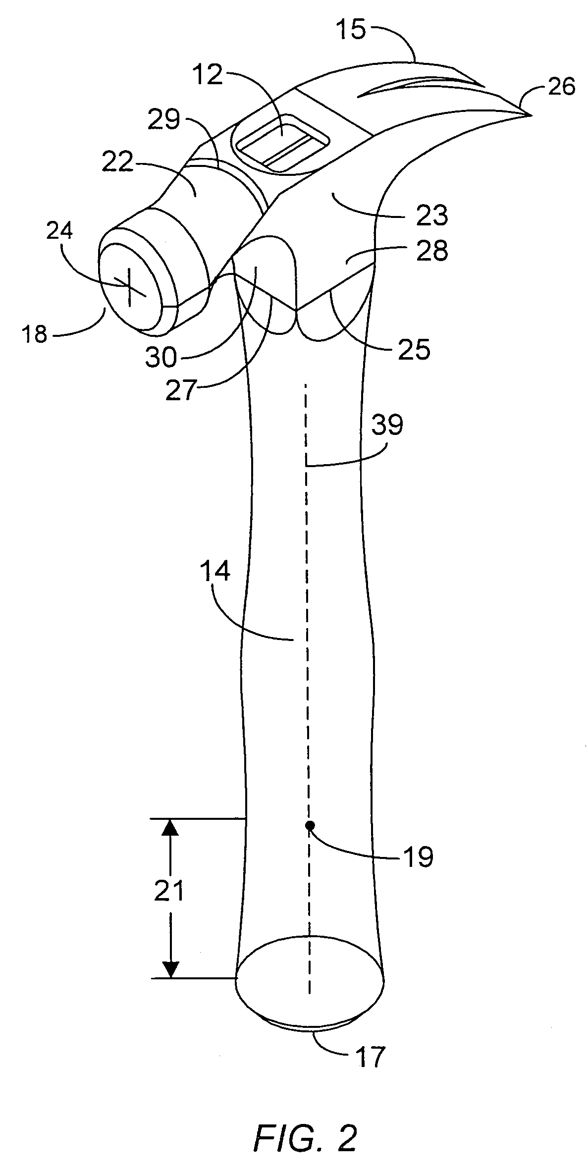
[0055]A claw hammer is depicted in FIG. 2. The claw hammer may include a grasping region 21 located on shank 14. The grasping region is preferably in the vicinity of end 17. The width of the shank in the grasping region may be increased or decreased relative to portions of the shank that lie outside of the grasping region. The grasping region may include one or more indentions or curved surfaces to facilitate grasping of the shank. The end 17 or butt of the hammer may be slightly wider than the remainder of the shank to inhibit the shank from slipping out of the hand during use. The grasping region preferably begins at a location on or adjacent to the butt and preferably extends upwardly (i.e., towards head 12) a vertical distance of between about 3.5 inches and about 4.5 inches, and more preferably a vertical distance between about 3.8 inches and about 4.2 inches. The grasping region preferably terminates at a location beyond which the hammer could not be grasped and used efficient...


PUM


Abstract

An impact instrument for delivering an impulse to an object. The impact instrument may include an impact surface for contacting the object and an elongated member extending from the impact surface that terminates in an end. The elongated member may include a grasping region in the vicinity of the end. When the instrument is grasped within the grasping region, the center of percussion of the instrument preferably coincides with the impact surface. The instrument may also contain pivoting grasping member disposed on the elongated member. A cavity is preferably formed between the grasping member and the elongated member and may contain compressible material. The grasping member may rigidly contact the elongated member at an ideal pivot point. The grasping member is preferably adapted to pivot with respect to the elongated member at the ideal pivot point. The pivoting of the grasping member preferably increases the amount of impulse delivered to an object, decreases vibration experienced by the user of the instrument, and reduces counter-rotational forces imparted from the instrument to the user. The impact instrument may be a hammer, ax, golf club, tennis racket, or similar device.

Description

CROSS REFERENCE TO RELATED APPLICATIONS[0001]The present application is a continuation of application Ser. No. 09 / 773,757, entitled “IMPROVED HAMMERING DEVICE,” filed on Jan. 29, 2001 (now abandoned), which is a continuation of application Ser. No. 08 / 951,573, entitled “IMPROVED HAMMERING DEVICE,” filed on Oct. 16, 1997 (now U.S. Pat. No. 6,755,096), based on provisional application Ser. No. 60 / 028,636 filed on Oct. 18, 1996, and provisional application Ser. No. 60 / 043,681 filed on Apr. 14, 1997.BACKGROUND OF THE INVENTION[0002]1. Field of the Invention[0003]The present invention generally relates to impact instruments including hammering devices such as claw hammers, ball-pein hammers, axes, hachets, sledges, and the like, and also including recreational devices such as croquet rackets, badmitten racquets, tennis racquets, racquetball racquets, golf clubs, baseball bats, softball bats, cricket bats, hockey sticks, and the like. An embodiment of the invention relates to an impact in...

Claims


Application Information

Patent Timeline
Patent Type & Authority Patents(United States)
IPC IPC(8): B25D1/00A63B49/08B25D1/12A63B53/14A63B59/00B25G1/01
CPCA63B59/0014B25G1/01B25D1/00B25D1/04A63B59/0092A63B49/08A63B53/14A63B59/0025A63B2243/0029A63B2243/0083A63B2102/32A63B2102/02A63B60/12A63B60/10A63B60/06A63B60/54A63B60/08A63B60/00
Inventor SCHRODER, KURT A.
Owner BOARD OF RGT THE UNIV OF TEXAS SYST
Why Eureka
Try Eureka