Remotely controllable fastening device

a remote control, fastening technology, applied in the direction of threaded fasteners, screws, mechanical devices, etc., can solve the problems of large number of rotations, multitude of different engagement geometries (catch profiles), and components cannot be assembled or disassembled

Active Publication Date: 2018-06-12
TCHOUANGUEU JACQUES
View PDF12 Cites 1 Cited by
  • Summary
  • Abstract
  • Description
  • Claims
  • Application Information

AI Technical Summary

Benefits of technology

[0033]By using a fluidic drive which is assigned to the fastening device, detaching, and optionally fastening, of the fastening device can take place very fast. Special tools are not necessary, since the actuation takes place by loading the drive with pressure (typically, with over pressure). Since in the case of several fastening devices, the same can be commonl

Problems solved by technology

A disadvantage of the known fastening devices is that, depending on the length of thread and thread pitch, they need a large number of rotations in order to eventually reach their end position (fastened state), or in order to be fully turned outwards from their counterpiece.
A further disadvantage lies in the multitude of different engagement geometries (catch profiles).
Since connecting devices with different engagement geometries are often used on one component, an according number of different tools must be provided; otherwise, the components can not be assembled or disassembled.
A common problem is the damage of the engagement geometries when screwing, but, at the latest, when unscrewing the fastening device from the fastening base, effected by too high screw-in forces.
The previously mentioned electrically actuatable fastening devices can only produce small forces, so that they can be used only in such situations where the forces necessary for detaching are small.
The chemically actuatable fastening means have the disadvantage that they are either actuatable only once, or that they have at least very long switching times.
A further disadvantage lies in the known fact that after a ce

Method used


Image

  • Remotely controllable fastening device
  • Remotely controllable fastening device
  • Remotely controllable fastening device

Examples


Embodiment Construction

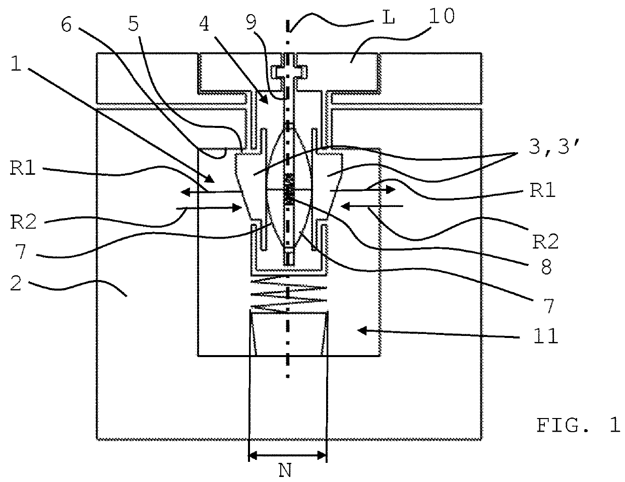
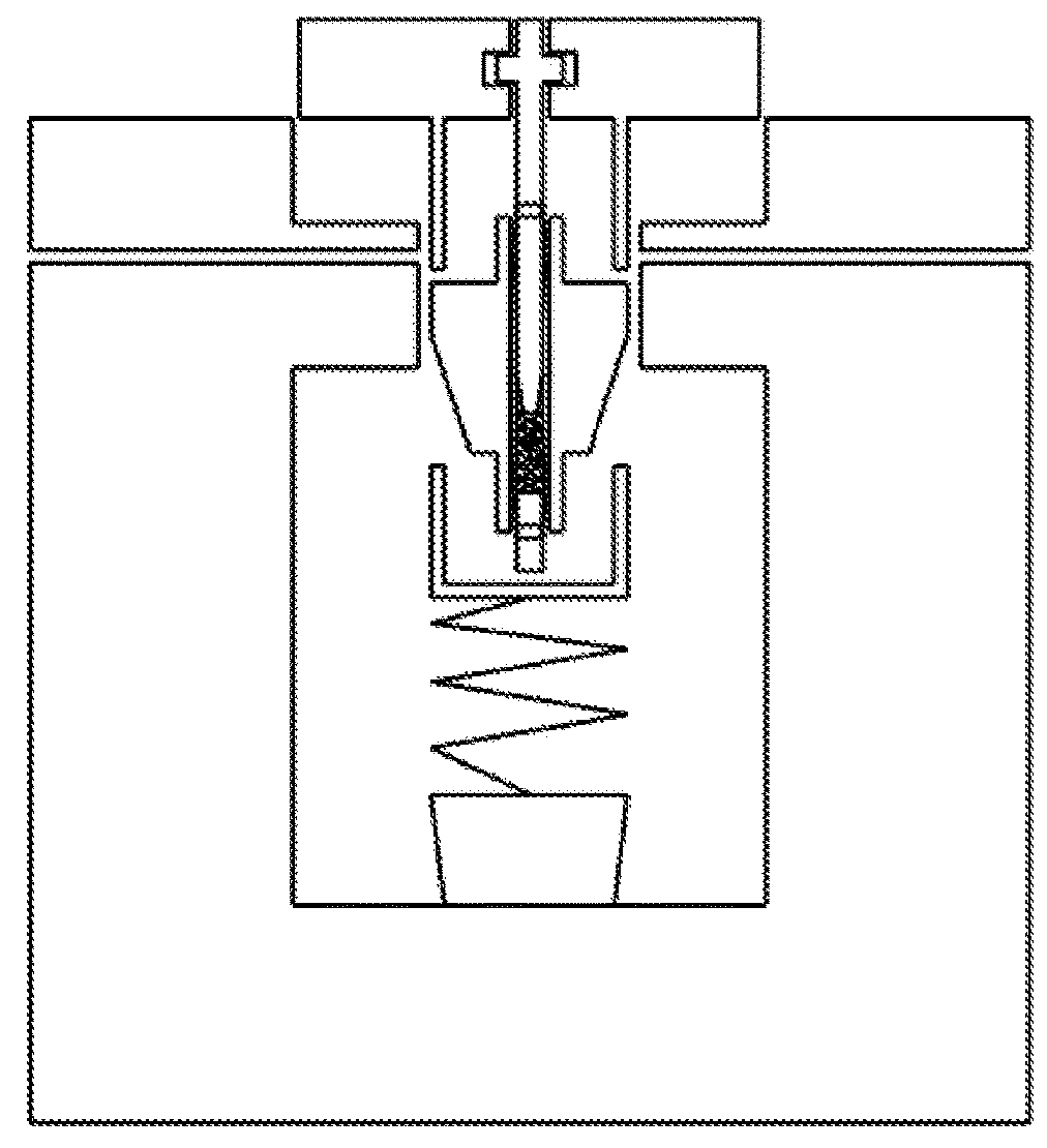
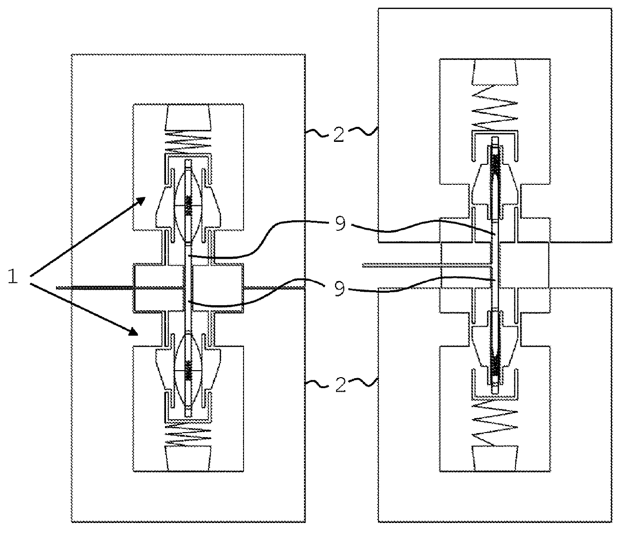
[0055]FIG. 1 shows an embodiment of the first main type of the fastening device according to the invention. The longitudinal axis L runs through it in vertical direction; it is at the same time the insertion direction. The fastening body 1 is inserted into a fastening base 2 which can be one component. The fastening body 1 has an anchor 3 which is multipart (individual parts 3′). In particular, the anchor 3 is designed to be insertable into the fastening base 2.

[0056]The anchor 3 is suitable for the form-closing and / or frictional anchoring of the fastening device in the fastening base 2. For this, it is movable in at least one first direction R1; presently, this are two first directions R1, since both individual parts 3′ are movable radially outwards. For the disengaging of the anchor 3, the individual parts 3′ are respectively moveable in a second direction R2 which is contrary to this first direction R1.

[0057]For this, the anchor 3 is connected with a remote operatable drive 4, th...


PUM


Abstract

A remotely controllable fastening device for the detachable connection of components has a longitudinal axis and at least one fastening body for insertion into a fastening base, wherein the fastening body has an anchor which is insertable into the fastening base, wherein, for the form-closing and/or frictional anchoring of the fastening device in the fastening base, the anchor is moveable in at least a first direction, and wherein, for the disengaging of the fastening device, the anchor is respectively moveable in a second direction which is contrary to the first direction, and wherein the anchor is connected with a drive which is remote operatable and which is provided for operation with a fluid and which is internally arranged, the anchor being moveable by the drive in at least the second direction.

Description

CROSS-REFERENCE TO RELATED APPLICATIONS[0001]This application is a national phase entry under 35 U.S.C. § 371 of international application serial no. PCT / IB2014 / 058612, filed Jan. 28, 2014, which claims priority to German patent application serial no. DE 10 2013 100 400.6, filed Jan. 29, 2013; the content of each is herein incorporated by reference in its entirety.TECHNICAL FIELD[0002]The invention relates to the field of mounting technique. More particular, the invention relates to the field of detachable screw-like fastening devices.BACKGROUND OF THE INVENTION[0003]Fastening devices for the detachable connecting of objects are known for a long time in the form of bolted connections. Here, a first moveable (separately present) body presently called “fastening body” is connected to a suitable second body presently called “fastening base” by means of rotating relative motion. The second body can be movable (mobile) as well, or it can essentially be stationary (immobile).[0004]The fas...

Claims


Application Information

Patent Timeline
IPC IPC(8): F16B21/06F16B1/00F16B19/10F16B5/02F16B13/06
CPCF16B21/06F16B1/005F16B1/0057F16B19/109F16B5/02Y10T24/45482F16B13/063F16B2200/91F16B2200/89
Inventor TCHOUANGUEU, JACQUES
Owner TCHOUANGUEU JACQUES
Why Eureka
Try Eureka