Rotary drive device comprising load-dependent brakes

a technology of rotary drive and load-dependent brakes, which is applied in the direction of couplings, slip couplings, gearing, etc., can solve the problem of not having a mechanism which provides, and achieve the effect of preventing discontinuous braking characteristics and increasing impulses in the movement characteristics of the driven sha

Active Publication Date: 2018-02-15
STABILUS
View PDF8 Cites 1 Cited by
  • Summary
  • Abstract
  • Description
  • Claims
  • Application Information

AI Technical Summary

Benefits of technology

[0013]In this way, after the coupling element has occupied the second position, a constant second braking force is applied, which is smaller than the above-mentioned first braking force in the first position of the coupling element, until the difference in torque between the drive shaft and the driven shaft has fallen below the above-mentioned second threshold value. In this way, when the difference in torque changes in a small range around the first threshold value, the coupling element is prevented from repeatedly transitioning from the first position into the second position and back into the first position, which could lead to discontinuous or juddery braking characteristics of the rotary drive device and thus to increased impulses in the movement characteristics of the driven shaft.
[0014]Furthermore, optionally, in a similar manner, a second threshold value can also be assigned to each of the plurality of second positions so that when a specific second position having a predetermined braking force is reached, the transition back to the adjacent position having a greater braking force takes place only after falling below said second threshold value, by means of which the above-mentioned advantage of preventing discontinuous braking characteristics by frequently jumping between adjacent positions in each of the plurality of second positions can be ensured.
[0015]In one embodiment, the transmission device can further comprise a drive transmission element which is connected to the drive shaft for conjoint rotation and in a stationary manner, and a driven transmission element which is connected to the driven shaft for conjoint rotation and in such a way that it can be displaced along the driven shaft, the coupling element being connected to the driven transmission element for conjoint rotation and in a stationary manner. This configuration represents a particularly simple option for displacing the coupling element between different positions by displacing the driven transmission element between different positions and thus for achieving the desired braking characteristics of the rotary drive device.
[0016]In one development, the drive transmission element and the driven transmission element can be provided with at least one pair of cooperating angular faces which are configured to convert a relative rotation of the two transmission elements into a displacement of the driven transmission element along the driven shaft. In this way, by sliding the angular faces against one another, which is triggered by the difference in torque between the drive shaft and the driven shaft, the displacement of the driven transmission element along the driven shaft and thus of the coupling element with respect to the braking element can be achieved.
[0017]In this case, the relative rotation of the two transmission elements can be restricted to a predetermined maximum angle, for example by means of at least one pair of cooperating stops assigned to the two transmission elements. In this way, firstly an end position for the displacement of the coupling element with respect to the braking element can be provided, and secondly slippage between the drive transmission element and the driven transmission element and thus the drive shaft and the driven shaft can be prevented.

Problems solved by technology

In known generic devices, however, no mechanism is provided which provides, according to a difference in torque between the drive shaft and the driven shaft, a braking force against the rotational movement of the drive shaft or driven shaft in the rotary drive device.

Method used


Image

  • Rotary drive device comprising load-dependent brakes
  • Rotary drive device comprising load-dependent brakes
  • Rotary drive device comprising load-dependent brakes

Examples


Embodiment Construction

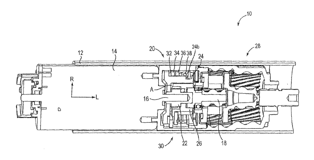
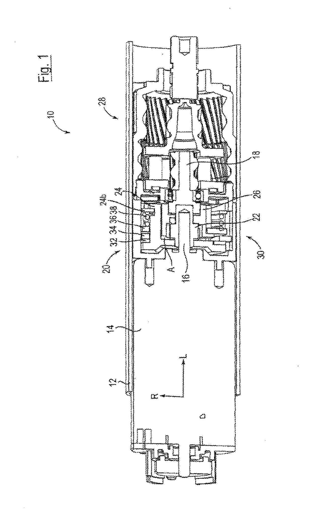
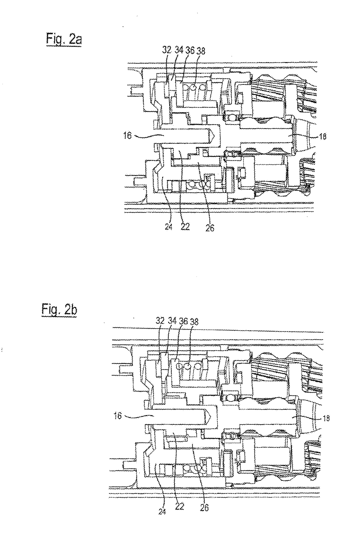
[0027]In FIG. 1, an embodiment of a rotary drive device according to the invention is denoted very generally by the reference sign 10. It comprises a cylindrical housing element 12 having a radial direction R and a longitudinal direction L, which accommodates, in the interior thereof, a motor assembly 14, a drive shaft 16 which can be driven by the motor assembly, a driven shaft 18 and a transmission device 20 for transmitting a torque from the drive shaft 16 to the driven shaft 18. In this case, the motor assembly 14 is a known electrically operated rotary motor, in which, if desired, another gear-system unit can be provided between the motor 14 and the drive shaft 16.

[0028]On the drive shaft 16, a drive transmission element 22 is located which is attached for conjoint rotation and in a stationary manner, and, seen from the drive shaft 16, a support element 24 is located radially further out on said shaft, which support element is likewise connected to said shaft for conjoint rotat...


PUM


Abstract

A rotary drive device includes a housing element, a drive shaft and a driven shaft, both rotatably mounted in the housing element, a transmission device that transmits torque from the drive shaft to the driven shaft, and a braking device configured to counteract rotation of the drive shaft. The braking device includes a drive shaft input element, a braking element connected to the housing element for conjoint rotation, and a coupling element adjustable with respect to the input element. A braking force exerted by the braking device is greater when the coupling element is located in a first position than when located in a second position, and the coupling element assigned to the driven shaft so that adjustment from the first position to the second position is triggered by exceeding a threshold value of the difference in torque between the drive shaft and the driven shaft.

Description

BACKGROUND[0001]The present invention relates to a rotary drive device, comprising a housing element, a drive shaft which is rotatably mounted in the housing element, a driven shaft which is rotatably mounted in the housing element, and a transmission device for transmitting a torque from the drive shaft to the driven shaft.[0002]Rotary drive devices of this type are generally known. Said devices can be used firstly to provide a rotational movement on the driven shaft, which then drives additional components of a superordinate construction, or for example also in cooperation with a device for converting the rotational movement of the driven shaft into a longitudinal movement, such as a worm gear or the like. Variable-length units of this type, in which a rotational movement of a drive shaft is converted by means of a driven shaft and furthermore a device for converting the rotational movement into a longitudinal movement for varying the length of the unit as a whole, are used in par...

Claims


Application Information

Patent Timeline
Patent Type & Authority Applications(United States)
IPC IPC(8): F16D67/00F16D55/22F16D59/00
CPCF16D67/00F16D59/00F16D2129/04F16H1/28F16D2127/005F16D55/22F16H35/00F16H2035/006F16H35/10F16D7/044F16D2125/38F16D7/028F16D7/024
Inventor RITTER, ANDREASARENZ, BERNDHILLEN, JORGBATOSKY, OLEG
Owner STABILUS
Why Eureka
Try Eureka