Retainer ring for wire package

a technology of wire package and ring, which is applied in the direction of web handling, transportation and packaging, manufacturing tools, etc., can solve the problems of affecting the operation, facing difficulty, and causing tangles, so as to reduce the effectiveness of restraining wire movemen

Inactive Publication Date: 2007-02-20
LINCOLN GLOBAL INC
View PDF24 Cites 55 Cited by
  • Summary
  • Abstract
  • Description
  • Claims
  • Application Information

AI Technical Summary

Benefits of technology

[0006]In accordance with the present invention, the standard weighted retainer ring, as shown in Cooper U.S. Pat. No. 5,819,934, is formed from a thin flat, flexible permanent magnet sheet. Thus, the welding wire new package includes a cylindrical drum with a central axis and containing multiple layers of looped welding wire defining the wire stack to be paid out, which body has an upper ring shaped surface with an outer cylindrical surface generally matching the drum and an inner cylindrical surface defining a central bore concentric with the drum axis. The wire body is overlaid with a flexible permanent magnet ring on the top of the upper ring shaped surface. This magnet retainer ring allows welding wire to be paid out from under the ring and upwardly from the central bore of the welding wire body loaded into the drum. The flexible magnet sheet is a standard commercial product; however, its use as a retainer ring for a welding wire package involves cutting the commercial sheet into a ring shape having an outer periphery covering or overhanging the wire stack and an inner periphery which is generally circular and matches the inner surface of the stored welding wire stack. In a test for creation of e script tangles, where the drum is rotated to create tangles and the length of wire between tangles is measured, it has been found that a standard weighted retainer ring, such as shown in Cooper U.S. Pat. No. 5,819,934, allowed such tangles at a rate of at least 25–30 times as frequent as a retainer ring constructed in accordance with the present invention. Indeed, by rotating the drum or wire and paying out the wire in an effort to cause such tangles, an e tangle often was not created during the duration of a standard test run when using the present invention. The reason for this improved performance appears to be that the flexible magnet sheet is held magnetically against the top of the magnetic wire and is pulled upwardly only in the area where the wire exits from the looped welding wire body. The external twist caused by feeder does not disturb the order of wire loops under the ring easily because the loops are held in place by magnetic force. The wire loops are less likely to pop out prematurely or become “out-of-order”—the order by which it was wound. Consequently, control of the wire movement under the ring is maintained during the payout operation. Furthermore, when using a standard retainer ring, the ring is shifted over the top of the wire in an orbit motion determined by the circumferential location from which the wire is being pulled. The present invention does not allow movement of the ring over the top of the welding wire to thereby open space between the ring and the drum to cause tanglements. These distinctive characteristics of the present invention drastically reduce the amount of tangles of the payout wire and thus is a substantial improvement over existing, standard weighted retainer rings.
[0009]Another object is to provide robust and intimate contact to the top of the wire stack from its flexible and magnetic nature, thus avoiding pitfalls of the rigid steel or plastic ring which can be lifted at one side by the force of the wire loses partial contact with the wire stack and decrease its effectiveness of restraining wire movement.
[0010]Still a further object of the present invention is the provision of a retainer ring, as defined above, which retainer ring is fairly inexpensive, easy to manufacture and does not add weight or complexity to the welding wire package.

Problems solved by technology

Lighter rings can be easily lifted by the wire during payout, thus losing its contact to the top of the wire stack; and thereby losing its intended purpose of restraining wire movement at the top of the wire stack.
This is the pitfall of the weighted ring design, essentially facing the difficulty of striking a balance of less tangle and less wire wobble.
Tangles are detrimental to the operation of the package since they cause down time of the robotic welding station.
Tangles are caused by many adverse movements of the wire loops on top of the wire stack.
Retainer rings so far on the market are not effective in preventing e script tangles.
This type of tangle is caused by poor alignment of drive rolls of the wire feeder that builds up back-twist in the wire as it feeds the wire.
The weighted retainer rings have not been successful in eliminating such tangles.

Method used


Image

  • Retainer ring for wire package
  • Retainer ring for wire package
  • Retainer ring for wire package

Examples


Embodiment Construction

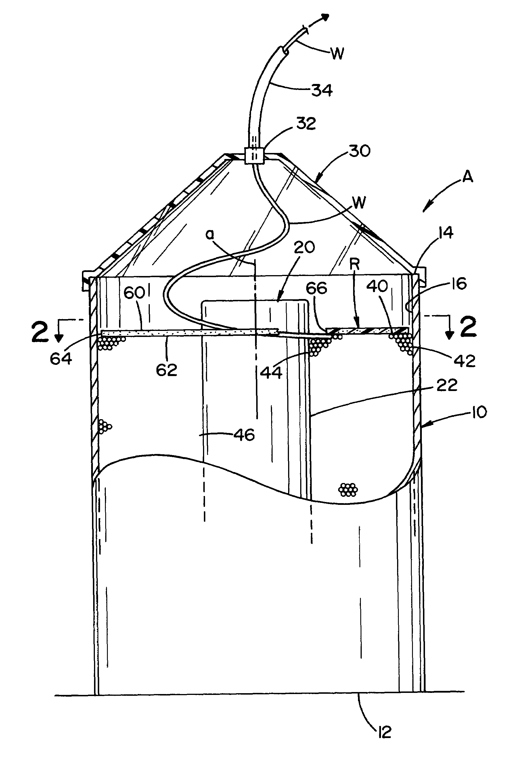
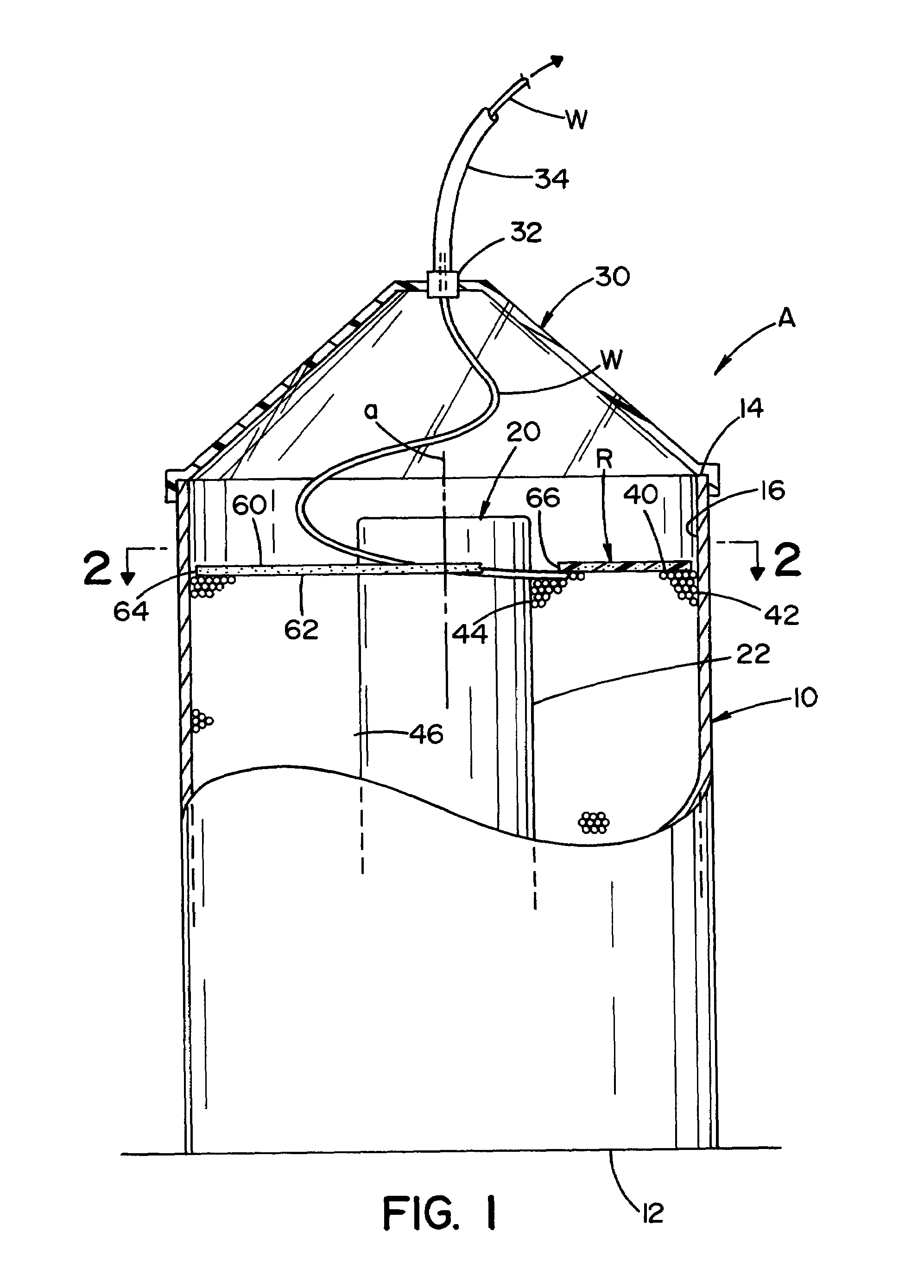
[0018]A standard welding wire drum type package is shown in FIGS. 1 and 2 wherein wire W is stored in and paid out of cylindrical drum 10 having a bottom 12, a top 14 and an inside diameter 16. In accordance with this type of drum it is common practice to use a cylindrical cardboard core 20 having an outer diameter 22. Inside surface 16 and outside surface 22 are cylindrical and concentric with central axis a of drum 10. At the welding facility, the top or lid of drum 10 (not shown) is removed and replaced with a feeding hat 30 including an upper grommet 32 communicated with a standard feed tube 34. Wire W is pulled from drum 10 during the welding operation. Package A is loaded at the wire manufacturing facility by being looped around core 20 to define a body of welding wire having a top surface 40, an outer cylindrical surface 42 against surface 16 and an inner cylindrical surface 44 against or close to surface 22. In this manner, a central vertically extending bore 46 is concentri...


PUM

PropertyMeasurementUnit
flexibleaaaaaaaaaa
thicknessaaaaaaaaaa
magnetic strengthaaaaaaaaaa

Abstract

A welding wire package comprising a cylindrical drum with a central axis, multiple layers of looped welding wire defining a wire stack to be paid out, said body having an upper ring shaped surface with an outer cylindrical surface generally covering or overhanging the wire stack and an inner cylindrical surface defining a central bore concentric with the drum axis and a flexible permanent magnet retainer ring on top of the upper ring shaped surface wherein the retainer ring allows welding wire to be paid from under the ring upwardly from the central bore.

Description

[0001]The present invention relates to a weld wire package and more particularly to an improved retainer ring for a loosely wound package, such as a fiber drum or cardboard box container or pail housing.INCORPORATION BY REFERENCE[0002]Welding wire used in high production operations, such as robotic welding stations, is provided in a package having over 200 pounds of wire. The package is often a drum where a large volume of welding wire is looped in the drum around a central core or a central clearance bore. During transportation and use the volume of loop wire in the drum is decreased. To control the transportation and payout of the wire, it is standard practice to provide an upper, weighted retainer ring. An early ring is shown in Kawasaki U.S. Pat. No. 4,869,367 wherein the ring slides by its own weight along the inner surface of the drum by outwardly extending resilient members. These members center the ring over the top of the loop wire so the wire can be pulled to the center an...

Claims


Application Information

Patent Timeline
Patent Type & Authority Patents(United States)
IPC IPC(8): B65H59/06B23K9/133B65H49/08
CPCB23K9/1333B65H59/06B65H49/08B23K9/124
Inventor HSU, CHRISTOPHERSTAVA, ELLIOT K.BARTON, DAVID J.
Owner LINCOLN GLOBAL INC
Why Eureka
Try Eureka