
Indirect evaporative cooling mechanism

a cooling mechanism and indirect technology, applied in the field of indirect evaporative cooling, can solve the problems of limited maximum cooling that can occur, limited evaporative cooling use, and commercial disadvantages of current systems, and achieve the effect of increasing efficiency, economy and productivity

Inactive Publication Date: 2005-10-06
MAISOTSENKO VALERIY +3
View PDF10 Cites 64 Cited by
  • Summary
  • Abstract
  • Description
  • Claims
  • Application Information

AI Technical Summary

Benefits of technology

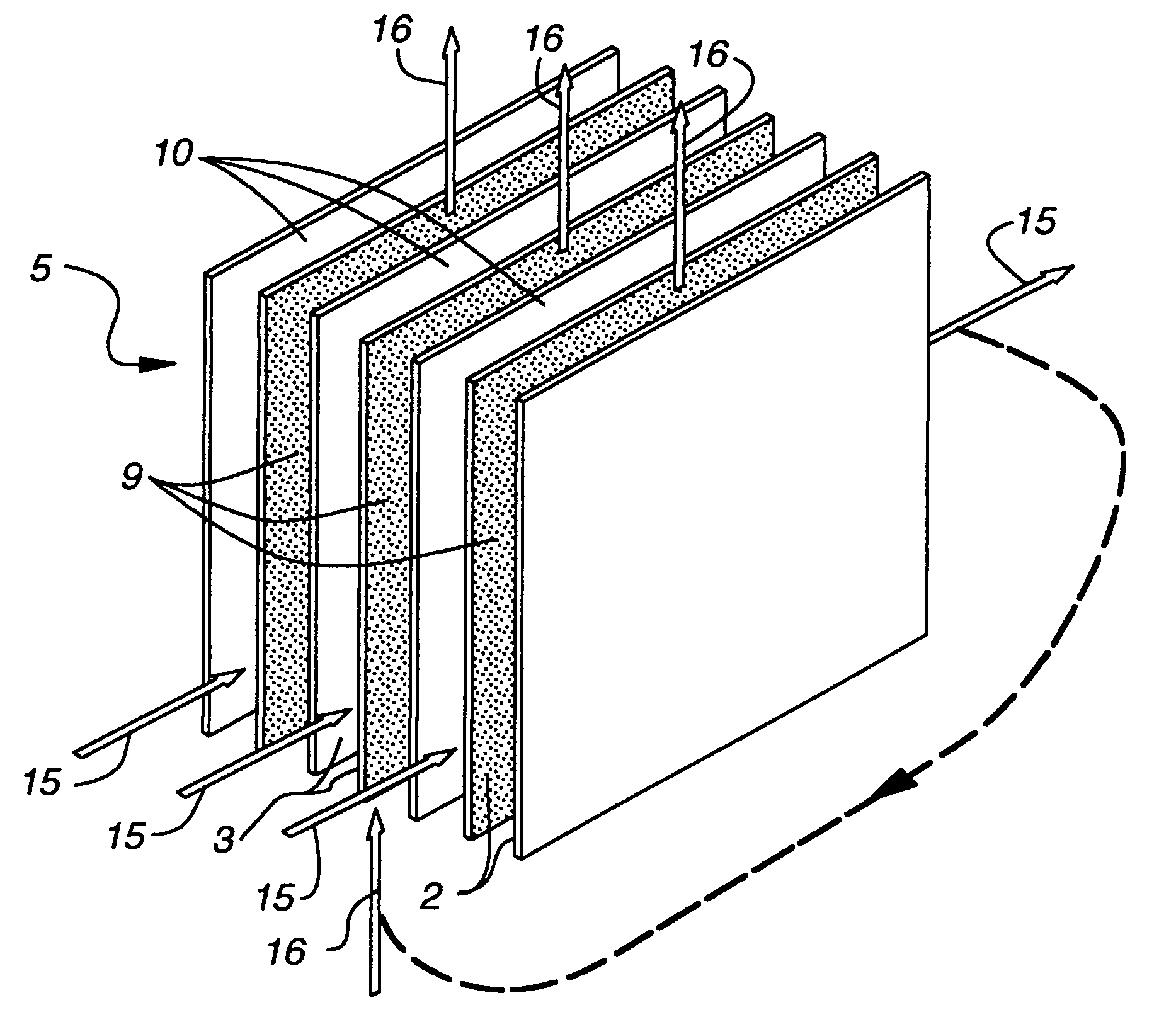
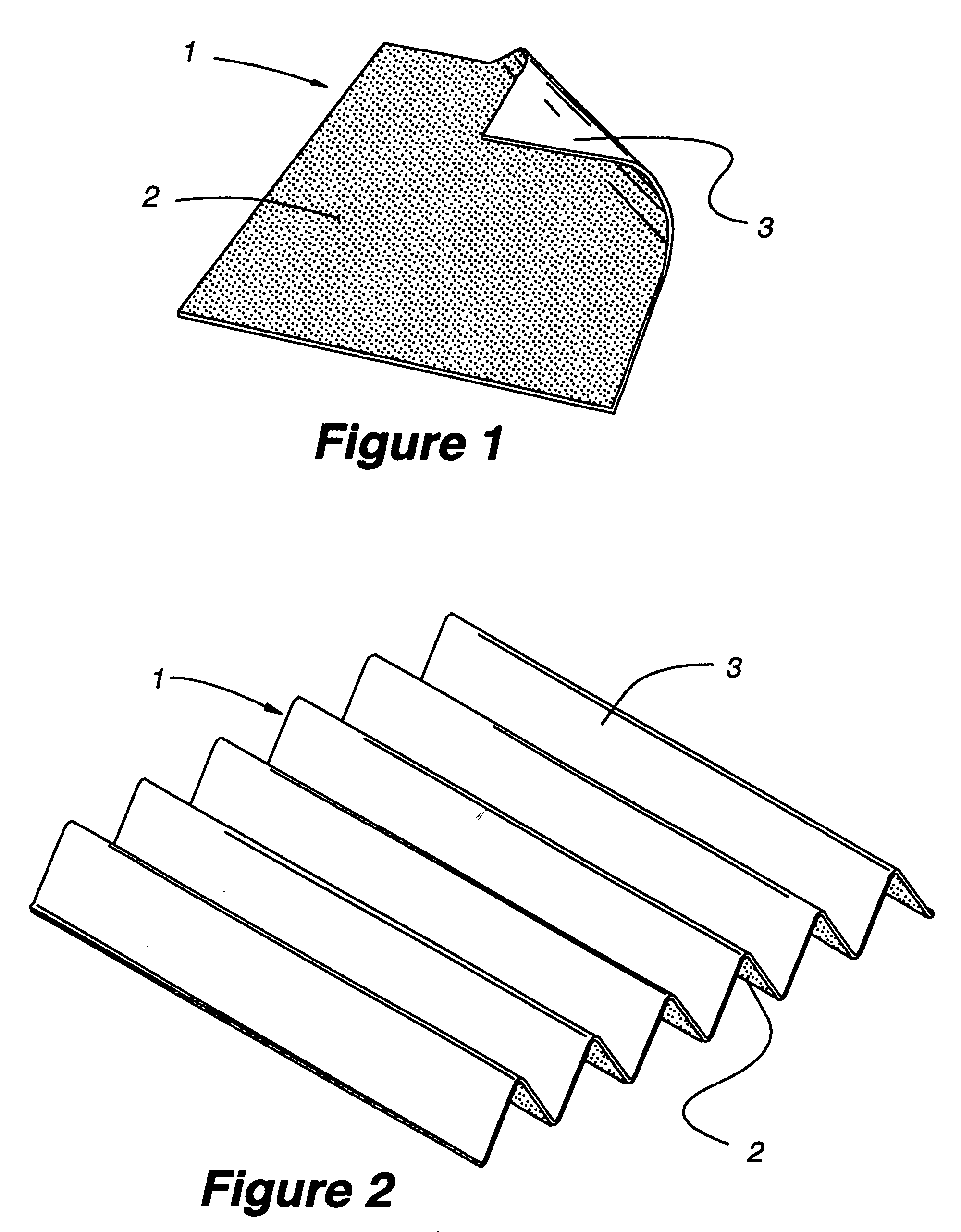
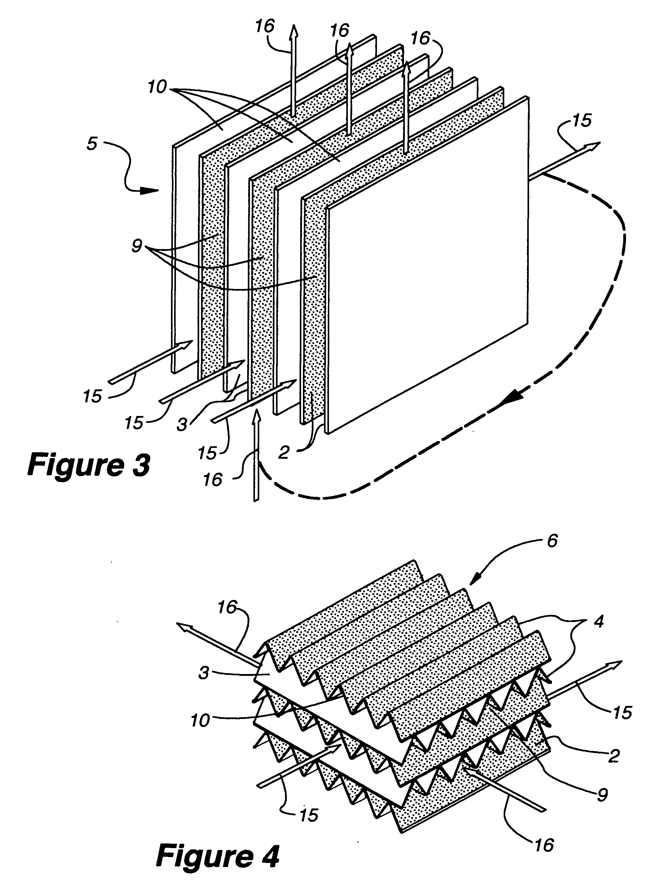
[0009] The particulars are directed to new structural elements that are sheets that are then formed as a stack or repetitive combination of sheets to create the cooling and heat transfer surfaces. The structure embodies thin plates or composite sheets made up of a layer that holds or wicks water or another fluid that is then released by way of evaporation. At least a portion of one side is a plastic or similar material or treatment that has low permeability to water or other evaporating fluid. The combination of these two provide heat conductivity across the barrier while still maintaining control of the fluid and any result in humidity to the air or other fluids that are being cooled. Also, the structure makes use of the physical characteristics of the materials to improve the mechanism.

Problems solved by technology

The available methods and apparatus have not addressed some of the limitations and as a result the use of evaporative cooling has been limited in some circumstances.
The limited maximum cooling that can occur has proved to be commercial disadvantages to the current systems.
Among the drawbacks to this method is the poor heat transfer that occurs with plastic of this thickness.
The disadvantage of this system is the inability to control the heat transfer in a desired way.
In addition to the heat transfer problems, the subject of this patent has the drawbacks of the weight, cost and potential corrosion of metal.

Method used


Image

  • Indirect evaporative cooling mechanism
  • Indirect evaporative cooling mechanism
  • Indirect evaporative cooling mechanism

Examples


Embodiment Construction

[0022] One component of an evaporative cooler system that is herein disclosed as an improved and novel component is the heat exchange surface. In prior systems of evaporative cooling the heat exchanger surface often was metal sheeting or plastic sheeting. As disclosed in the referenced patents the use of a metal sheet with a fluid layer has been used. The within invention makes use of a combination or composite sheeting or plate (1), but accomplishes and improves efficiency due to its selection and structure of materials.

[0023] The composite sheeting that is used in the within disclosure consists of two layers. The water-conducting layer that we call the wick layer (2), can be made of cellulose, polyester or other similar materials such as polypropylene or fiberglass. The preferred embodiment is of cellulose. Cellulose also has good wicking capabilities but may need structural or form support to keep it in a proper shape when it is wet, and to keep it from deforming when drying. In...


PUM


Abstract

The present invention relates to methods for indirect evaporative air-cooling with the use of plates, heat exchangers and feeder wicks—of the indirect evaporative type. Several components for an indirect evaporative heat exchanger described as follows: A plate for an indirect evaporative heat exchanger where the plate is made of laminate material having one sheet of wicking material for wet zone(s) and the other of a water proof plastic material for the dry zone(s). An evaporative heat exchanger is created by assembling the plates forming spacing for wet channels, (they are created by the wet zone of the plates,) and dry channels, (they are created by the dry zone of the plates,) with channel guides or corrugated plates. The spacing between the plates is defined to reduce pressure drop for increased airflow. A feeder wick system creates the wetting of the wet channels without excess water. Sometimes the wet zone of the plate can be made of a membrane material where the opposite side of this membrane material is covered by a solid desiccant creating the wet zone of this desiccant plate. An indirect evaporative heat exchanger that is created by assembling both wick coated with plastic plates and desiccant plates, can realize not only the evaporative cooling but also the dehumidification of air.

Description

[0001] The present application is a Continuation-in-Part of U.S. patent application Ser. No. 10 / 213,002, filed Aug. 5, 2002.FIELD OF ART [0002] The present invention relates to a method of indirect evaporative cooling with specific improvements to the apparatus, the heat exchangers, the fluid providing apparatus. The new improved apparatus described herein enable the use of evaporative coolers in efficient, economical and a variety of environments. BACKGROUND OF THE INVENTION [0003] The subject invention improves the efficiency, economic feasibility, and productivity of evaporative coolers. The specific improvements apply to the heat exchanger plates, and the use of wick methods to improve distribution of fluids and also aid the evaporative action. [0004] Evaporative cooling, as a means to cool, is a common method with a long history. The available methods and apparatus have not addressed some of the limitations and as a result the use of evaporative cooling has been limited in some...

Claims


Application Information

Patent Timeline
IPC IPC(8): F02B29/04F24F1/0059F28D5/00
CPCF02B29/0462F24F2001/0092Y02T10/146Y02B30/545F28D5/00F24F1/0007Y02T10/12F24F1/0059Y02B30/54
Inventor MAISOTSENKO, VALERIYGILLAN, LELAND E.HEATON, TIMOTHY L.GILLAN, ALAN D.
Owner MAISOTSENKO VALERIY
Learn More