Method of verifying corrected photomask-pattern results and device for the same

a technology of photomask-pattern and verification device, which is applied in the direction of photomechanical equipment, originals for photomechanical treatment, instruments, etc., can solve the problems of reducing the yield rate of semiconductor devices, exposure simulators, and inability to correct photomask-pattern lines,

Inactive Publication Date: 2007-08-07
KK TOSHIBA
View PDF7 Cites 4 Cited by
  • Summary
  • Abstract
  • Description
  • Claims
  • Application Information

AI Technical Summary

Benefits of technology

This approach enables precise verification of photomask-pattern corrections, reducing the time and effort required to achieve optimal photoresist patterns by detecting deviations and optimizing exposure conditions, thereby improving the yield and quality of semiconductor devices.

Problems solved by technology

Such a deviation of photoresist patterns from photomask-patterns deteriorates characteristics of semiconductor devices and / or the breaking down or forming of bridges of photoresist patterns causes substantially decline in yield rate of the semiconductor devices.
The exposure simulators, however, basically cannot correct a line width of photomask-patterns, for example.
Obviously, it takes a long time to correct photomask-patterns and is burdensome for the engineers to fix them satisfactorily.
In the OPC operation of photomask-patterns, one of its targets is to make OPC patterns but its output patterns do not always result in ideal ones for all the patterns, i.e., the OPC patterns are not always consistent with photoresist patterns transferred to a photoresist film.
In short, a prior art photomask-pattern correction device is merely provided with a function to make up OPC patterns and it is insufficient to verify functions as to whether pattern data are truly suitable for the transfer to a photoresist film.

Method used


Image

  • Method of verifying corrected photomask-pattern results and device for the same
  • Method of verifying corrected photomask-pattern results and device for the same
  • Method of verifying corrected photomask-pattern results and device for the same

Examples


first embodiment

[0050]FIG. 1 is an operation flow chart for lithography engineers to review OPC patterns by means of a method of verifying photomask-pattern-correction-results and / or a photomask-pattern-correction-result-verification device (collectively called the “correction verification system”) in accordance with the first embodiment of the present invention. First, layout patterns are read in the correction verification system for the review of OPC patterns (Step S201).

[0051]Next, a parameter input unit is accessed (Step S202). FIG. 2 shows the parameter input unit provided with three kinds of buttons 401-403, common parameter area 404 and function selector 405. The buttons are execution button 401 for carrying out a selected function to be described later, storage button 402 for storing parameters provided to the parameter input unit, and parameter read-in button 403 for reading in parameters from a parameter storage unit.

[0052]Common parameter area 404 includes subject region 404a to be proc...

second embodiment

[0117]FIG. 19 is an operation flow chart for layout engineers to review OPC operations by means of a method of verifying photomask-pattern-correction results and / or a photomask-pattern-correction-result-verification device in accordance with the second embodiment of the present invention. A layout pattern is read in for the review of such OPC operations (Step S301).

[0118]Next, a parameter input unit is accessed (Step S302). Details of the parameter input unit are substantially the same as those of the first embodiment and omitted here, accordingly.

[0119]Parameters are then read in from a layout-pattern-storage section (Step S303). A subject region is designated for the photomask-pattern-correction-result-verification operation (Step S304). One or more functions are selected from the six functions for the photomask-pattern-correction-result-verification operation and are instructed of the execution of such selected functions (Step S305). At this time, parameters required for each fun...


PUM

PropertyMeasurementUnit
angleaaaaaaaaaa
opticalaaaaaaaaaa
sizesaaaaaaaaaa

Abstract

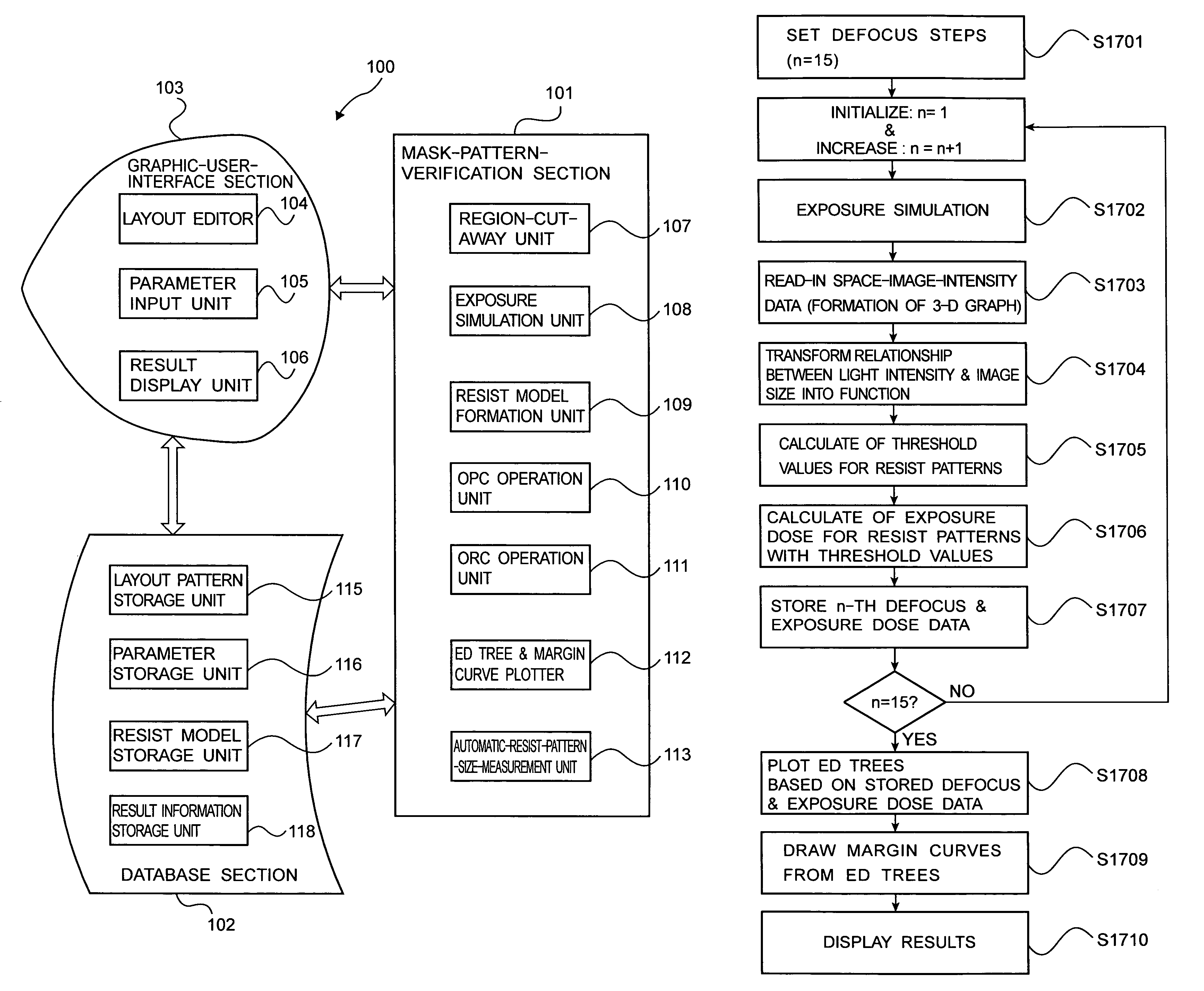
A method of verifying photomask-pattern-correction results includes steps of cutting away photomask patterns of a region to be subjected to correction, forming photoresist models used for execution of an optical-proximity-effect-correction operation, executing the optical-proximity-effect-correction operation of the photomask patterns with respect to the photoresist models, executing an exposure simulation for simulating photoresist patterns formed on a photoresist film to which the photomask patterns are transferred after the optical-proximity-effect-correction operation, and designating parameters required for executions of the cutting away the photomask patterns of the region, the forming of the photoresist models, the optical-proximity-effect-correction operation, and the exposure simulation.

Description

CROSS-REFERENCE TO RELATED APPLICATIONS[0001]This application is based upon and claims the benefit of priority from the prior Japanese Patent Application No. 2003-396868, filed on Nov. 27, 2003, the entire contents of which are incorporated in this application by reference.FIELD OF THE INVENTION[0002]This invention relates to a method of verifying corrected photomask-pattern results and a verification device for such corrected photomask-pattern results and, more particularly, to a method of verifying corrected photomask-pattern results applied to manufacturing large-scale-integrated-semiconductor circuits and a verification device for the same.BACKGROUND OF THE INVENTION[0003]Semiconductor devices become finer in structure as the integration of their integrated circuits is higher. As a result, optical proximity effects greatly influence differences between designed photomask-patterns, and photoresist patterns transferred from the designed photomask-patterns to a photoresist film on ...

Claims


Application Information

Patent Timeline
Patent Type & AuthorityPatents(United States)
IPC IPC(8): G06F17/50G03F1/36G03F1/68G03F1/70H01L21/027
CPCG03F1/144G03F1/36G03F7/70641G03F1/68
InventorINAZU, TAKATOSHI
OwnerKK TOSHIBA