Interferometric measuring device utilizing a slanted probe filter

a technology of interferometer and probe filter, which is applied in the direction of measurement devices, interferometers, instruments, etc., can solve the problems of additional difficulties during calibration and the difficulty of ensuring the durability of calibration

Inactive Publication Date: 2008-03-04
ROBERT BOSCH GMBH
View PDF3 Cites 8 Cited by
  • Summary
  • Abstract
  • Description
  • Claims
  • Application Information

AI Technical Summary

Benefits of technology

[0008]Using these measures, there comes about a similar effect as when using a partially transmitting or partially reflecting coating in the partially transmitting region. Because of the slanting faces in conjunction with the numerical aperture, in this context, the characteristics of the portion of radiation transmitted to the surface of the measuring object, and coming from it, as well as the portion of radiation reflected in the partially transmitting region, may be influenced in a suitable manner so as to achieve interference patterns that may be able to be optimally evaluated.

Problems solved by technology

In this context, it is difficult to ensure the durability of a calibration.
In connection with fitting in a glass plate to compensate for optical asymmetries, too, additional difficulties come about during the calibration.
A costly construction is connected with these difficulties, an exact adjustment to the properties of the measuring probe being also required.

Method used


Image

  • Interferometric measuring device utilizing a slanted probe filter
  • Interferometric measuring device utilizing a slanted probe filter
  • Interferometric measuring device utilizing a slanted probe filter

Examples


Embodiment Construction

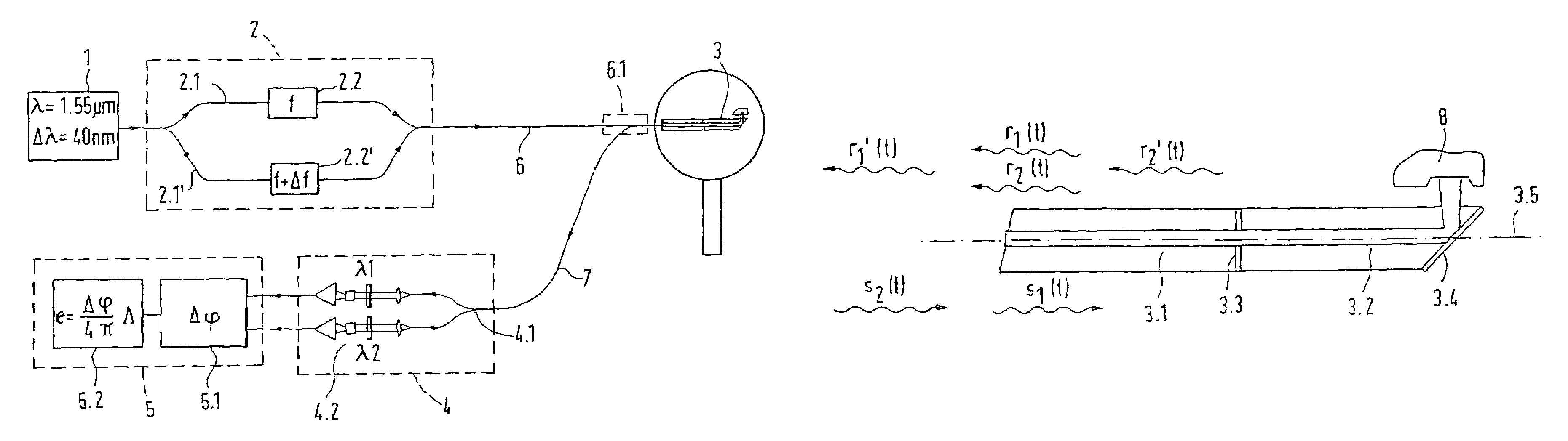
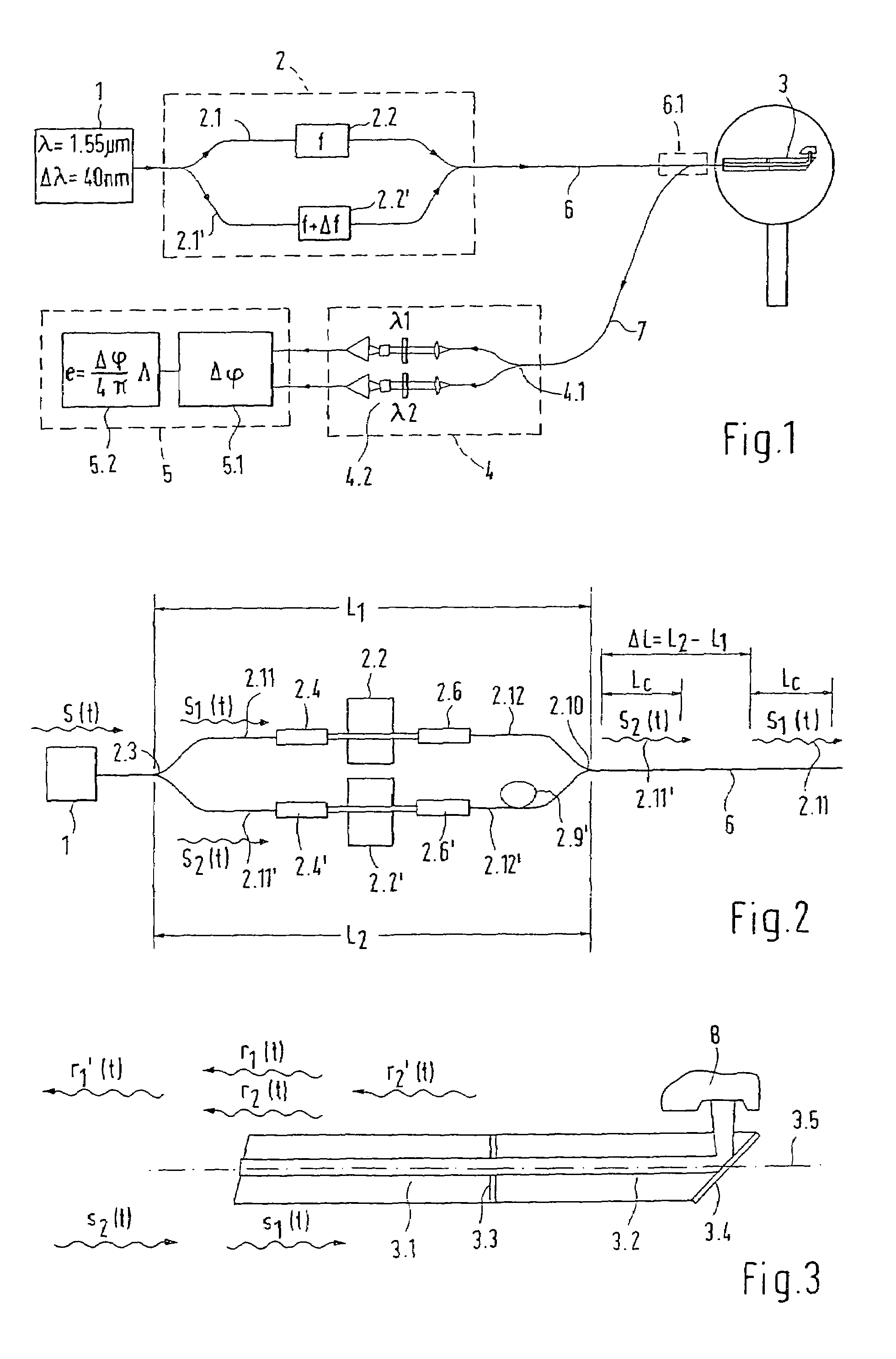
[0021]As shown in FIG. 1, the interferometric measuring device based on the principle of heterodyne interferometry has a broad-band, short-coherent light source 1, whose radiation is supplied to a so-called modulating interferometer 2. In modulating interferometer 2, which is shown in greater detail in FIG. 2, radiation s(t) is split up at a first beam splitter 2.3 into a first beam component 2.1 guided via a first arm, having a partial radiation s1(t) and a second beam component 2.1′ guided via a second arm, having a partial radiation s2(t), and is recombined at the exit side at an additional beam splitter 2.10, and from there it is conducted via a light-conducting fiber device 6 to a distant measuring probe.

[0022]From measuring probe 3, which is constructed, for example, as a Fizeau interferometer or a Mirau interferometer, as is explained in more detail in the documents named at the outset, the radiation subsequently reaches, via an additional light-conducting fiber device 7, a r...


PUM


Abstract

An interferometric measuring device for recording shape, roughness or separation distance of the surface of a measuring object, having a modulating interferometer, to which is supplied short coherent radiation by a radiation source, having a measuring probe that is spatially separated from the modulating interferometer and is coupled to it via a light-conducting fiber set-up, in which combined beam components are split in a common arm in a partially transmitting region into measuring and reference beams, and having receiver and evaluating devices for converting the supplied radiation into electrical signals and for evaluating the signals based on phase difference. A construction for reliable measurements even in tight hollow spaces provides that the partially transmitting region is formed by a slanting exit face of a probe fiber at an exit angle as to the optical probe axis and a likewise slanting entrance face, of a fiber section following on the object side, as to the optical probe axis at an entrance angle, a wedge-shaped gap being formed between the exit and entrance surfaces.

Description

FIELD OF THE INVENTION[0001]The present invention relates to an interferometric measuring device for recording the shape, the roughness or the separation distance of the surface of a measuring object using a modulation interferometer, to which a radiation source supplies short-coherent radiation and which has a first beam splitter for splitting the radiation supplied into a first beam component guided via a first arm and into a beam component guided via a second arm, of which the one is shifted with respect to the other, with the aid of a modulation device, in its light phase or light frequency, and passes through a delay line, and which are subsequently combined at an additional beam splitter of the modulation interferometer, and having a measuring probe, that is spatially separated from the modulation interferometer and is coupled or able to be coupled to the latter, in which the combined beam components are split up in a common arm in a partially transmitting region into a measur...

Claims


Application Information

Patent Timeline
Patent Type & Authority Patents(United States)
IPC IPC(8): G01B9/02G01B11/24
CPCG01B11/2441G01B9/02064G01B9/02057G01B9/02002G01B9/0205G01B9/0209G01B2290/45
Inventor DRABAREK, PAWELBREIDER, DOMINIQUEDUVOISIN, MARC-HENRIMARCHAL, DOMINIQUE
Owner ROBERT BOSCH GMBH
Why Eureka
Try Eureka