Check patentability & draft patents in minutes with Patsnap Eureka AI!

Control system, surface, and control device

a control system and control device technology, applied in the direction of burglar alarm mechanical actuation, instruments, electric signalling details, etc., can solve the problem of high maintenance level of the system, and achieve the effect of reducing the avoiding the unnecessary power consumption of the display 340

Inactive Publication Date: 2008-04-22
FUJIFILM BUSINESS INNOVATION CORP
View PDF11 Cites 2 Cited by
  • Summary
  • Abstract
  • Description
  • Claims
  • Application Information

AI Technical Summary

Benefits of technology

This solution reduces maintenance needs and enhances the accuracy and efficiency of object detection and control systems by eliminating battery replacement requirements and allowing for high-density sensor configurations.

Problems solved by technology

However, since a conventional wireless sensor needs a battery to operate, it is necessary to periodically replace the battery of the wireless sensor.
Therefore, if a system employs a lot of wireless sensors, a high degree of maintenance of the system is required.

Method used


Image

  • Control system, surface, and control device
  • Control system, surface, and control device
  • Control system, surface, and control device

Examples


Embodiment Construction

[0020]An embodiment of the present invention will be described with reference to the drawings.

1. Configuration

1-1. System Configuration

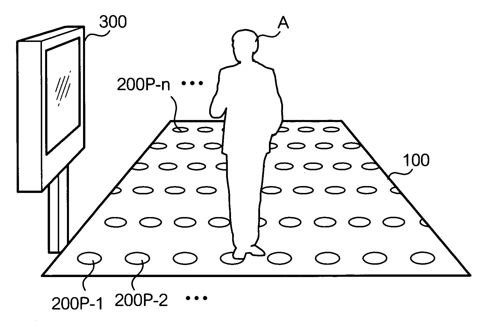
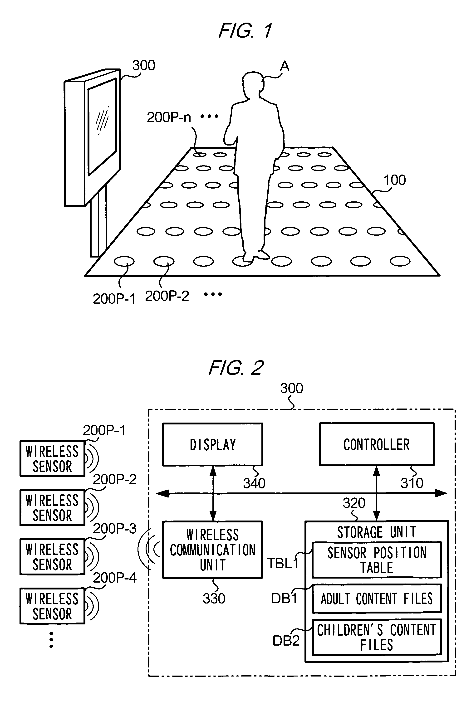
[0021]A configuration of a system according to the present embodiment will be described with reference to FIG. 1. In the drawing, the reference number 100 indicates a passable surface (hereinafter referred to as “surface 100”) laid out indoors or outdoors. The reference numbers 200P-1 to 200P-n indicate a small wireless pressure sensor which does not require a battery and which measures pressure applied on surface 100. Pressure sensors 200P-1 to 200P-n are evenly dispersed in surface 100 in a high-density configuration. Accordingly, surface 100 is capable of high-accuracy detection.

[0022]Since each of pressure sensors 200P-1 to 200P-n does not have a battery, and thus does not require replacement of a battery, it is small and inexpensive to maintain when compared to a conventional pressure sensor.

[0023]Pressure sensors 200P-1 to 200P-n, when receivin...


PUM


Abstract

The present invention provides a control system including: plural wireless measuring units, each of which, when receiving a radio signal, uses the signal as an energy source to measure a physical quantity, and generates and sends a radio signal having an attribute reflecting the measured physical quantity; a transmitter; a receiver; a storage unit which stores position data of the wireless measuring units in accordance with their identification data; a calculation unit which calculates physical quantities based on the received radio signals; a recognition unit which recognizes a distribution of the calculated physical quantities with reference to position data stored in accordance with identification data specified by the received radio signals; an identifying unit which identifies a state of an object on the surface based on the distribution of the recognized physical quantities; and a control unit which performs a control depending on the state of the identified object.

Description

[0001]This application claims priority under 35 U.S.C. §119 of Japanese Patent Application No. 2005-84901 filed on Mar. 23, 2005, the entire content of which is hereby incorporated by reference.BACKGROUND OF THE INVENTION[0002]1. Field of the Invention[0003]The present invention relates to a technique for sensing the presence or absence of an object or the state of an object.[0004]2. Description of the Related Art[0005]In recent years, a system has been developed in which a wireless sensor is caused to sense the presence or absence of an object or the state of an object indoors or outdoors, and a control is performed on the basis of a result of the sensing. For example, in Japan Unexamined Patent Publication No. 2004-515757, it is disclosed that wireless sensors are located in a building, and air conditioning or lighting in the building is controlled on the basis of a result of sensing by the wireless sensors, that wireless sensors are located in a home and used for security, and th...

Claims


Application Information

Patent Timeline
Patent Type & Authority Patents(United States)
IPC IPC(8): G08B13/00G01D21/00G08C15/00G08C17/00
CPCH04Q9/00
Inventor KOSHIMIZU, MINORUWATANABE, MASAOFUNO, HIROYUKIIIDA, KIYOSHIMIZUTANI, RYOTASAITO, YASUNORIISHII, TSUTOMUHOTTA, HIROYUKIHAYASHI, NAOKI
Owner FUJIFILM BUSINESS INNOVATION CORP
Features
  • R&D
  • Intellectual Property
  • Life Sciences
  • Materials
  • Tech Scout
  • Unparalleled Data Quality
  • Higher Quality Content
  • 60% Fewer Hallucinations
Learn More