Magnetic mounting apparatus

Active Publication Date: 2008-05-20
CARNEVALI JEFFREY D
View PDF17 Cites 145 Cited by
  • Summary
  • Abstract
  • Description
  • Claims
  • Application Information

AI Technical Summary

Benefits of technology

[0009]The adapter plate cooperates with the transition between the support surface and surrounding frame or lip of the magnetic mounting platform to: during assembly, guide the adapter plate into the socket with its substantially flat mounting surface coextensive with and flush against the recessed support surface; and during disassembly, to release the adapter plate from the attractive grip of the magnet when relative twisting of the adapter plate causes the edges of the adapter plate to travel along the transition between the support surface and surrounding frame or lip of the magnetic mounting platform. Acco

Problems solved by technology

These and other known magnetic mounting platforms each suffer limitations that limit their usef

Method used


Image

  • Magnetic mounting apparatus
  • Magnetic mounting apparatus
  • Magnetic mounting apparatus

Examples


Embodiment Construction

[0020]In the Figures, like numerals indicate like elements.

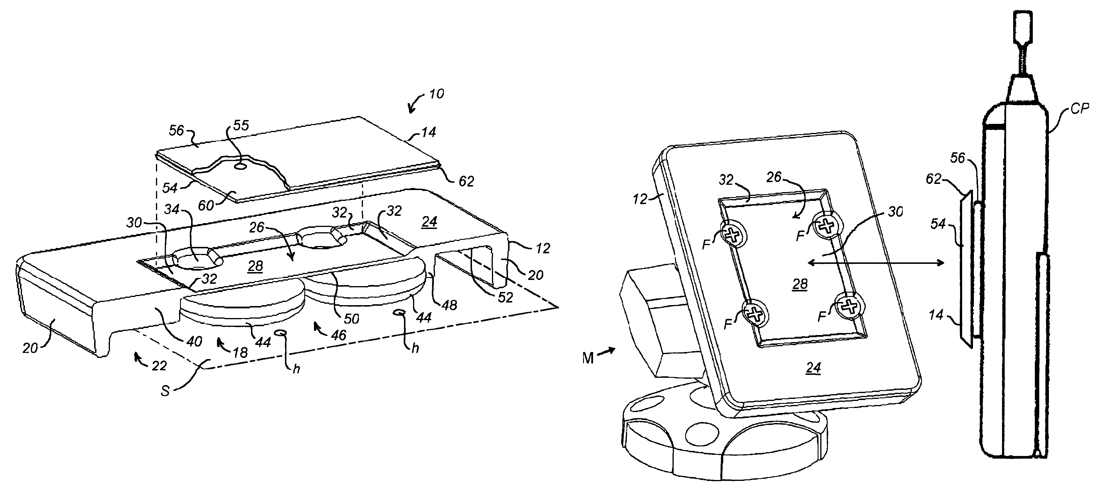
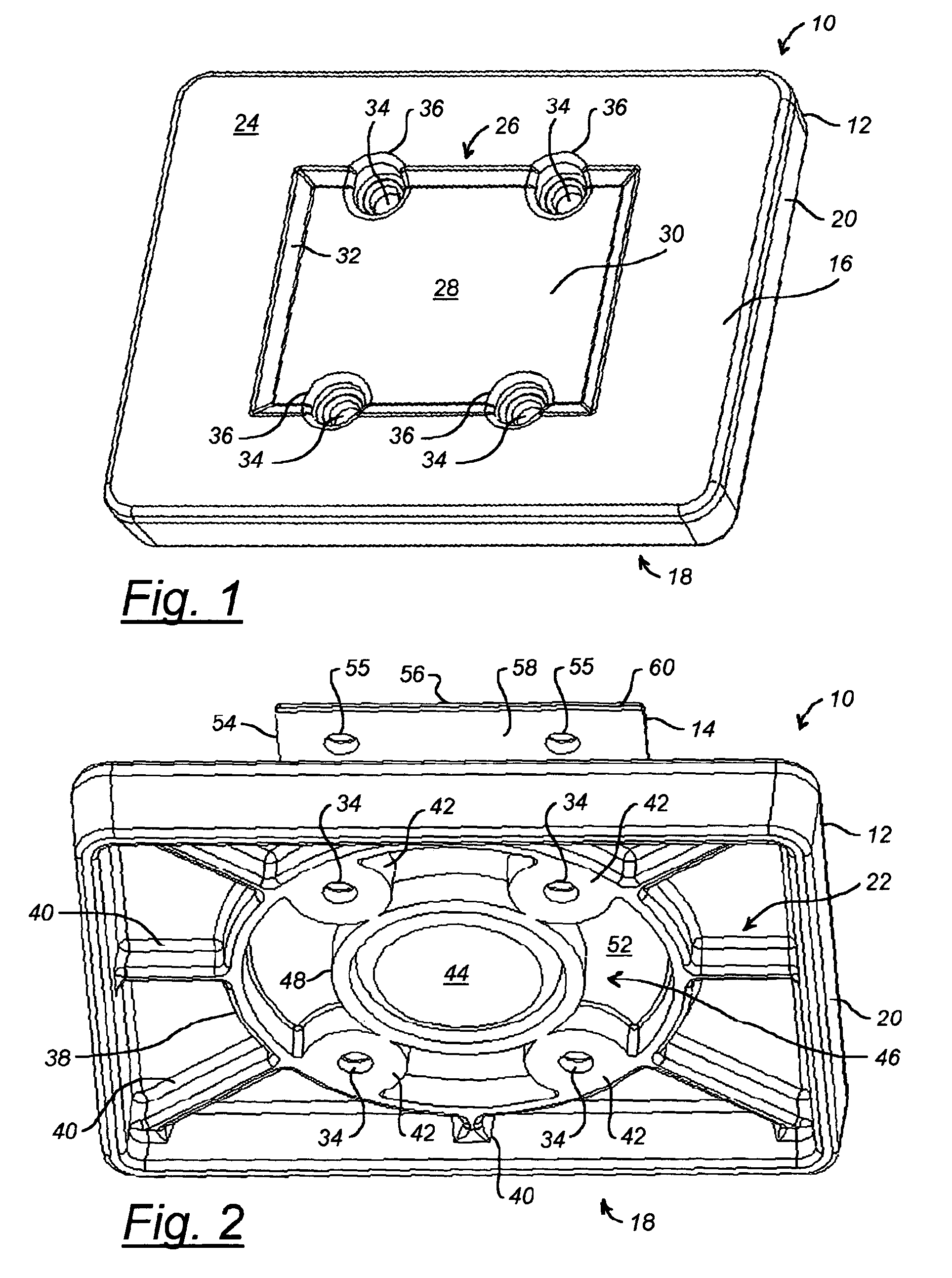
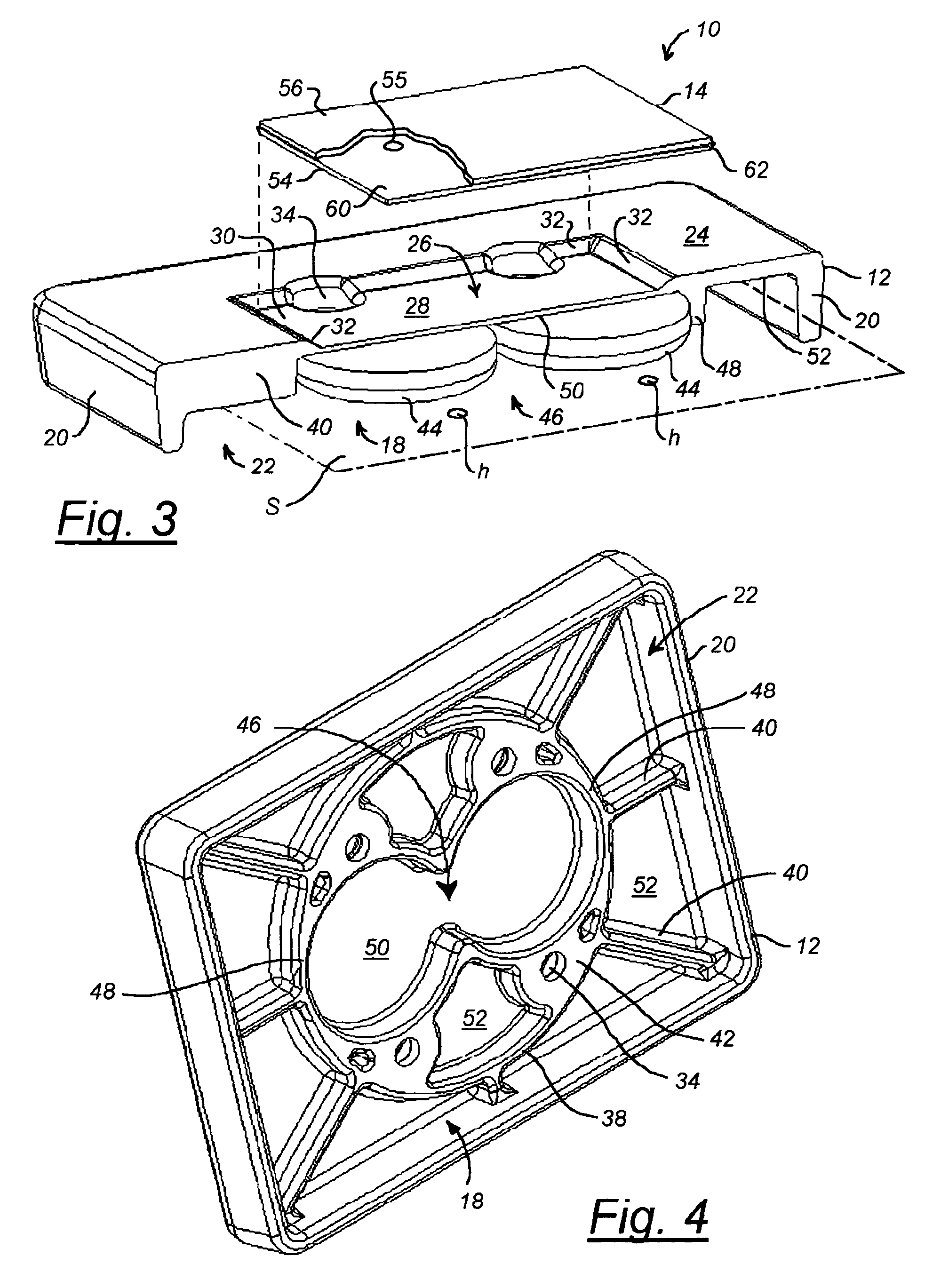
[0021]The present invention is a magnetic mounting apparatus for removably retaining different handheld devices by means of magnetic attraction. The magnetic mounting apparatus of the invention being formed of a magnetic mounting platform in combination with a magnetically permeable adapter plate. The magnetic mounting platform of the invention provides a shallow socket of a generally rectangular or specifically square configuration having at its base a substantially flat support surface that is recessed relative to a substantially flat surrounding frame or lip with a transition wall between the support surface and surrounding frame or lip. According to one embodiment of the invention, the transition wall is optionally outwardly inclined between the support surface and surrounding frame or lip. The lip and recessed support surface are backed by a rigidly reinforcing interface structure that also operates as means for securin...


PUM


Abstract

An apparatus for removably retaining by magnetic attraction any of various modem handheld devices. The magnetic mounting apparatus provides a magnetic mounting platform having a socket-like recessed support surface surrounded by a raised lip and backed by an interface structure that secures the magnetic mounting platform assembly to an external mounting surface. A permanent magnet is disposed within a cavity that positions magnet in close proximity to the flat support surface. A separate and distinct ferromagnetic adapter plate is adhered to a device to be supported, the adapter plate being structured for accommodation by the socket-like recessed support surface for removably retaining the device by magnetic attraction to the magnetic mounting platform.

Description

[0001]This application is related to and claims priority benefit of co-pending U.S. patent application Ser. No. 10 / 402,064 entitled, “MAGNETIC MOUNTING PLATFORM,” filed in the name of Jeffrey D. Carnevali on Mar. 27, 2003, the complete disclosure of which is incorporated herein by reference.FIELD OF THE INVENTION[0002]The present invention relates to the field of device mounting platforms, and in particular to handheld device mounting platforms operable by means of magnetic attraction.BACKGROUND OF THE INVENTION[0003]Mounting platforms for handheld devices and other small articles operable by means of magnetic attraction are generally well-known. Several of these magnetic mounting platforms are known for supporting handheld cell phones on the dashboard of an automobile. One example is shown in U.S. Pat. No. 5,992,807 entitled, UNIVERSAL MAGNETIC STAND FOR CELL PHONES, issued to Tarulli on Nov. 30, 1999, which is incorporated herein by reference, which describes a magnet that is perm...

Claims


Application Information

Patent Timeline
IPC IPC(8): A47G1/17F16M11/04F16M11/14
CPCF16M11/04F16M13/00F16M2200/022
Inventor CARNEVALI, JEFFREY D.
Owner CARNEVALI JEFFREY D
Why Eureka
Try Eureka