Magnetic buckle

Active Publication Date: 2022-02-17
LIAN YANG PLASTIC (SHEN ZHEN) CO LTD
View PDF0 Cites 2 Cited by
  • Summary
  • Abstract
  • Description
  • Claims
  • Application Information

AI Technical Summary

Benefits of technology

[0029]The beneficial effect of the present invention is that: it effectively solves the above problems. The magnetic buckle of the present invention is provided with moving portions that are pressed oppositely with dual-directional operations, which is ergonomic and simple to operate. Moreover, when the moving portions are pressed in two directions, the unlocking portion disposed inside may be inserted between the parts where the lock tongue is combined with the buckle base assembly, thereby reducing the attraction between the magnets and facilitating user to separate the lock tongue from the lock hole quickly and effortlessly in the next step to achieve the unlocking effect. In addition, in the present invention, through the provision of the connecting arm and the elastic arm, the adjusting portion may not only expand in the radial direction but also move in the axial direction, so that the lock tongue may easily press the adjusting portion into the lock hole under the action of a small magnetic attraction, thereby reducing requirements for the magnetic strength of the first magnet and the second magnet. Further, in the present invention, by arranging the free end of the unlocking portion into a wedge surface shape, it may not only be pressed between the lock tongue and the bottom of the first magnet mounting slot for separation to greatly reduce the magnetic attraction, but also may move the first magnet

Problems solved by technology

However, users often need to hold the child in one hand and operate the safety buckle with the other hand.
Therefore, this kind of plug-in safety buckle is relatively inconvenient to operate, and it cannot meet requirements of various scenarios.
For this kind of magnetic buckle, it has to be pressed hard to unlock, which either requires both hands to operate to unlock, or will apply pressure on the occupant as well as with the help of lifting, and the magnetic force has to be overcome so that a greater force is required to lift to unlock during lifting; therefore, the actua

Method used


Image

  • Magnetic buckle
  • Magnetic buckle
  • Magnetic buckle

Examples


Embodiment Construction

[0044]In order to enable the above objects, features and advantages of the disclosure to be more apparent and easily understood, the specific embodiments of the disclosure will be further elaborated hereafter in connection with the drawings.

[0045]The following embodiments are further explanations and supplements to the present invention, and do not constitute any limitation to the present invention.

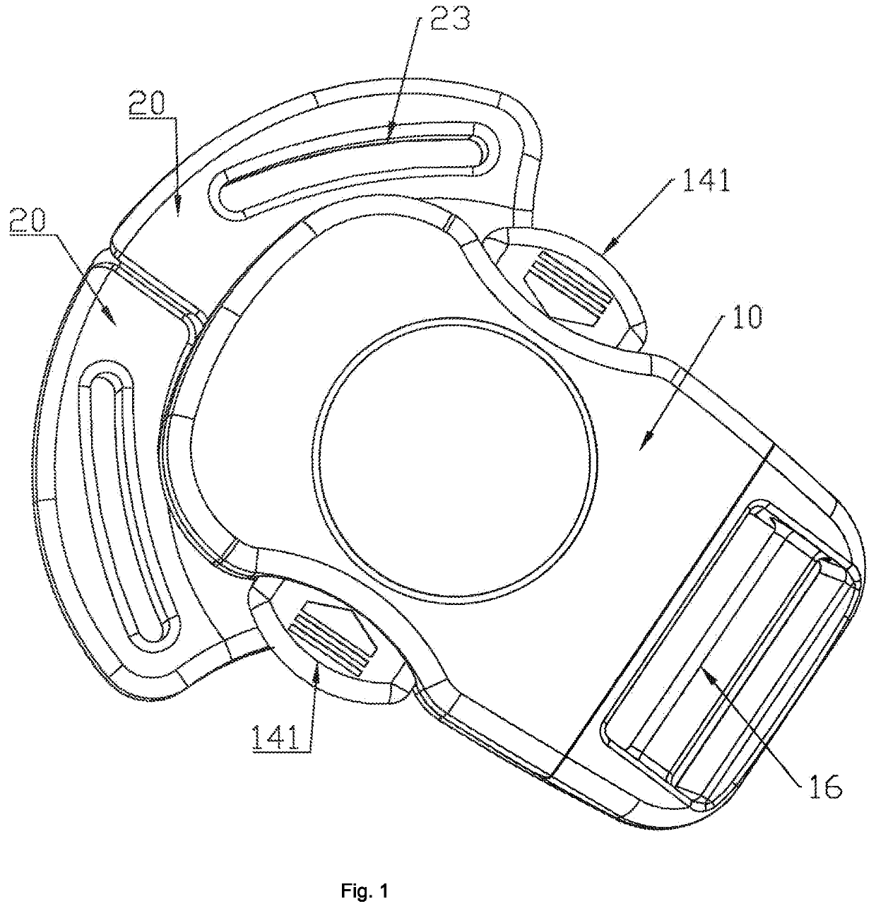
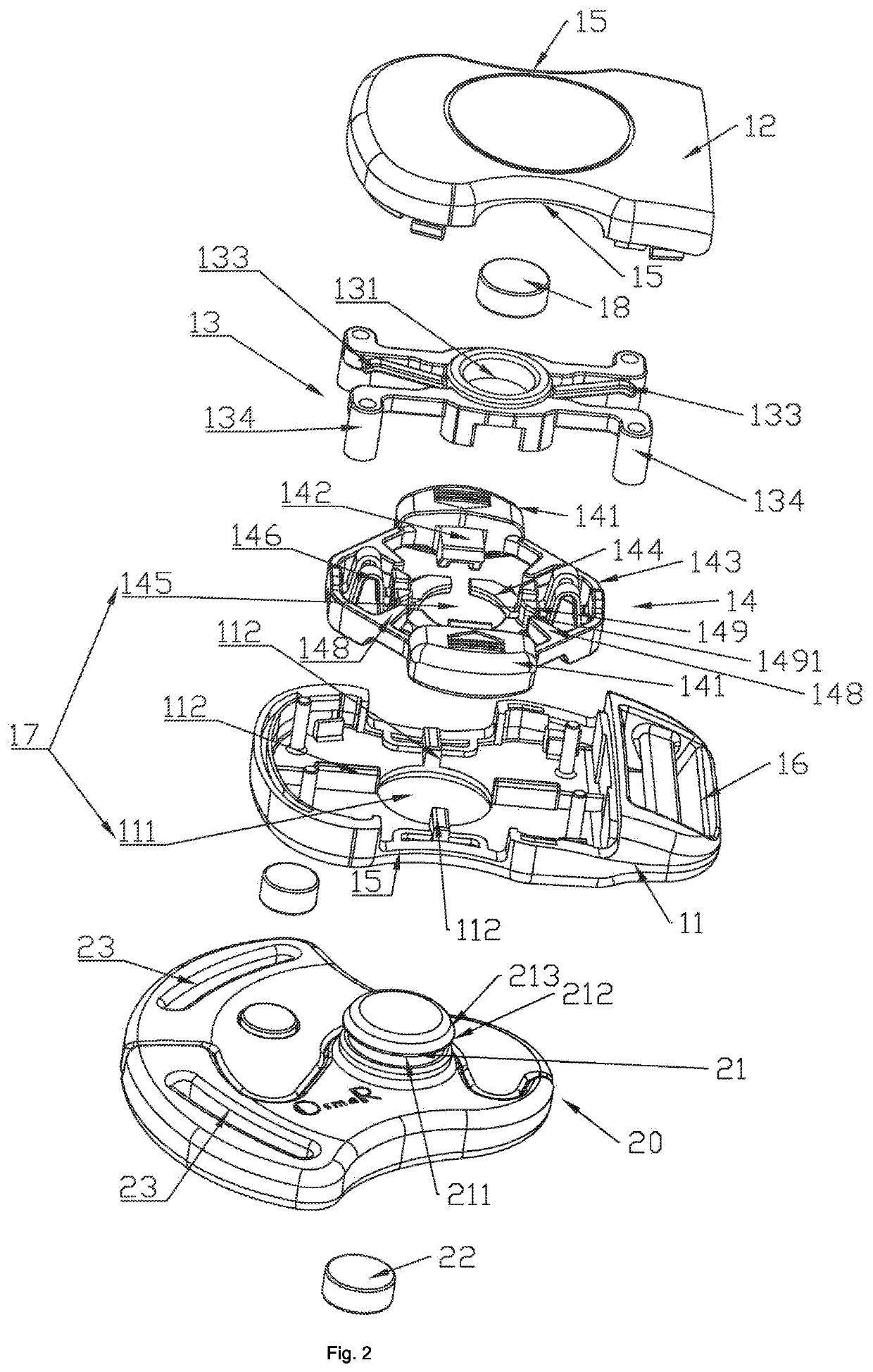
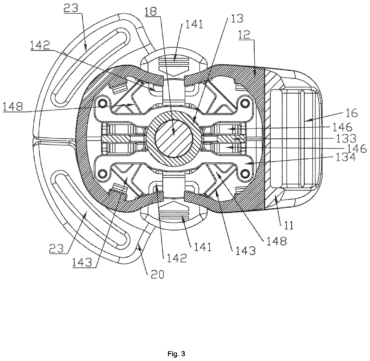
[0046]As shown in FIGS. 1 to 13, one main point of the magnetic buckle of the present invention lies in pressing on both sides to unlock, wherein when pressed, an internal unlocking portion 142 may be inserted between two portions attracted by magnets to separate the two portions to weaken the magnetic force of the magnets, thereby facilitating unlocking. In addition, the other main point of the magnetic buckle of the present invention lies in that a functional portion disposed inside the magnetic buckle may force a lock hole 17 to expand, so as to facilitate the unlocking, thereby avoidi...


PUM


Abstract

A magnetic buckle including a buckle base assembly and a locking assembly is disclosed. A first magnet and an adjustable lock hole are disposed on buckle base assembly, a lock tongue and a second magnet are disposed on locking assembly, two moving portions are disposed at the buckle base assembly respectively, and two unlocking portions are disposed within the buckle base assembly. When the lock hole is close to the lock tongue, the first magnet attracts the second magnet to guide the lock tongue into the lock hole to achieve locking. When the moving portions are pressed toward each other, the unlocking portions move toward the lock tongue to separate the parts of the lock tongue combined with the buckle base assembly for reducing an attractive force between the first magnet and the second magnet, so as to facilitate separation between the buckle base assembly and the locking assembly.

Description

BACKGROUND OF THE INVENTIONField of the Invention[0001]The present invention relates to a buckle, in particular to a magnetic buckle that is easy to operate and conforms to ergonomics.Description of Related Art[0002]Some parts of children's products such as child strollers, child safety seats, and infant carriers usually need to be connected or maintained in a certain state through buckles. For example, the infant carrier needs to be connected and loosened, so this variable state connection can be realized through buckles. Normally, most of the buckles are plug-in safety buckles. This plug-in safety buckle requires the user to align and lock the mating male buckle and female buckle with both hands to achieve a safe connection. However, users often need to hold the child in one hand and operate the safety buckle with the other hand. Therefore, this kind of plug-in safety buckle is relatively inconvenient to operate, and it cannot meet requirements of various scenarios. Thus, magnetic...

Claims


Application Information

Patent Timeline
IPC IPC(8): A44B11/26
CPCA44B11/266A44D2203/00A44B11/258A44B11/2523
Inventor LI, QIUZONG
Owner LIAN YANG PLASTIC (SHEN ZHEN) CO LTD
Why Eureka
Try Eureka