Image sensor controller, electronic device, and method for controlling image sensor

a technology of image sensor and electronic device, which is applied in the direction of instruments, television systems, color signal processing circuits, etc., can solve the problems of unnecessarily long time for shift and transfer operations at the transfer section, and achieve the effect of shortening the time for shift and transfer operations and speeding up the image reading speed

Inactive Publication Date: 2008-06-24
138 EAST LCD ADVANCEMENTS LTD
View PDF23 Cites 1 Cited by
  • Summary
  • Abstract
  • Description
  • Claims
  • Application Information

AI Technical Summary

Benefits of technology

[0008]The present invention has been made in view of the technical problem described above. Accordingly, an object of this invention is to provide image sensor controllers, electronic devices and methods for controlling image sensors, which can shorten the time for shift and transfer operations, and thereby achieve a faster image reading speed.
[0009]Another object of the present invention is to provide image sensor controllers, electronic devices and methods for controlling image sensors, which can increase the degree of freedom in setting clock patterns to be supplied to an image sensor.SUMMARY OF THE INVENTION
[0012]As a result of increasing the frequency of the shift / transfer clock during the dummy pixel output period, the shift / transfer time at the transfer section can be shortened and a faster image reading speed can be achieved. In addition to changing the frequency of the shift / transfer clock during the dummy pixel output period, the rise timing, fall timing or clock duty of the clock pulse may also be changed.
[0014]As a result of increasing the frequency of the shift / transfer clock during the non-reading pixel output period, the shift / transfer time at the transfer section can be shortened and a faster image reading speed can be achieved. In addition to changing the frequency of the shift / transfer clock during the non-reading pixel output period, the rise timing, fall timing or clock duty of the clock pulse may also be changed.
[0022]In accordance with other embodiments, the image processing controller may disable an output operation of the A / D converter during periods in which the A / D converter outputs image data obtained from the dummy pixel region and non-reading pixel region. By so doing, the image processing controller does not have to receive image data during these output periods.
[0025]In accordance with other embodiments, the present invention relates to an image sensor controller that controls an image sensor having a light receiving section and a transfer section that receives image data from the light receiving section. The image sensor controller comprises a drive controller that supplies to the transfer section, which shifts and transfers received image data, a shift / transfer clock for shifting and transferring the image data. The drive controller includes a pattern selector that selects, from among a plurality of clock patterns for setting shift / transfer clock, a specific clock pattern for each period during which image data is outputted from the transfer section of the image sensor. The frequency of the shift / transfer clock supplied during a particular period is based on the specific clock pattern selected for that period. Thus, different clock patterns are selected according to output periods of the transfer section, and shift / transfer clocks based on the respective selected clock patterns are supplied to the transfer section of the image sensor. As a result, the degree of freedom in setting shift / transfer clocks to be supplied to the image sensor can be improved.

Problems solved by technology

However, conventional image sensor controllers use only a fixed transfer clock pattern to drive an image sensor.
As a result, the time for shift and transfer operations at the transfer section is unnecessarily long.

Method used


Image

  • Image sensor controller, electronic device, and method for controlling image sensor
  • Image sensor controller, electronic device, and method for controlling image sensor
  • Image sensor controller, electronic device, and method for controlling image sensor

Examples


Embodiment Construction

[0049]The embodiments described below in conjunction with the drawings are not intended as limiting, but rather are presented as exemplary arrangements of the present invention. As will be appreciated by those skilled in the art, not all structure / operation described in the present embodiments is necessarily indispensable in implementing a solution provided by the present invention.

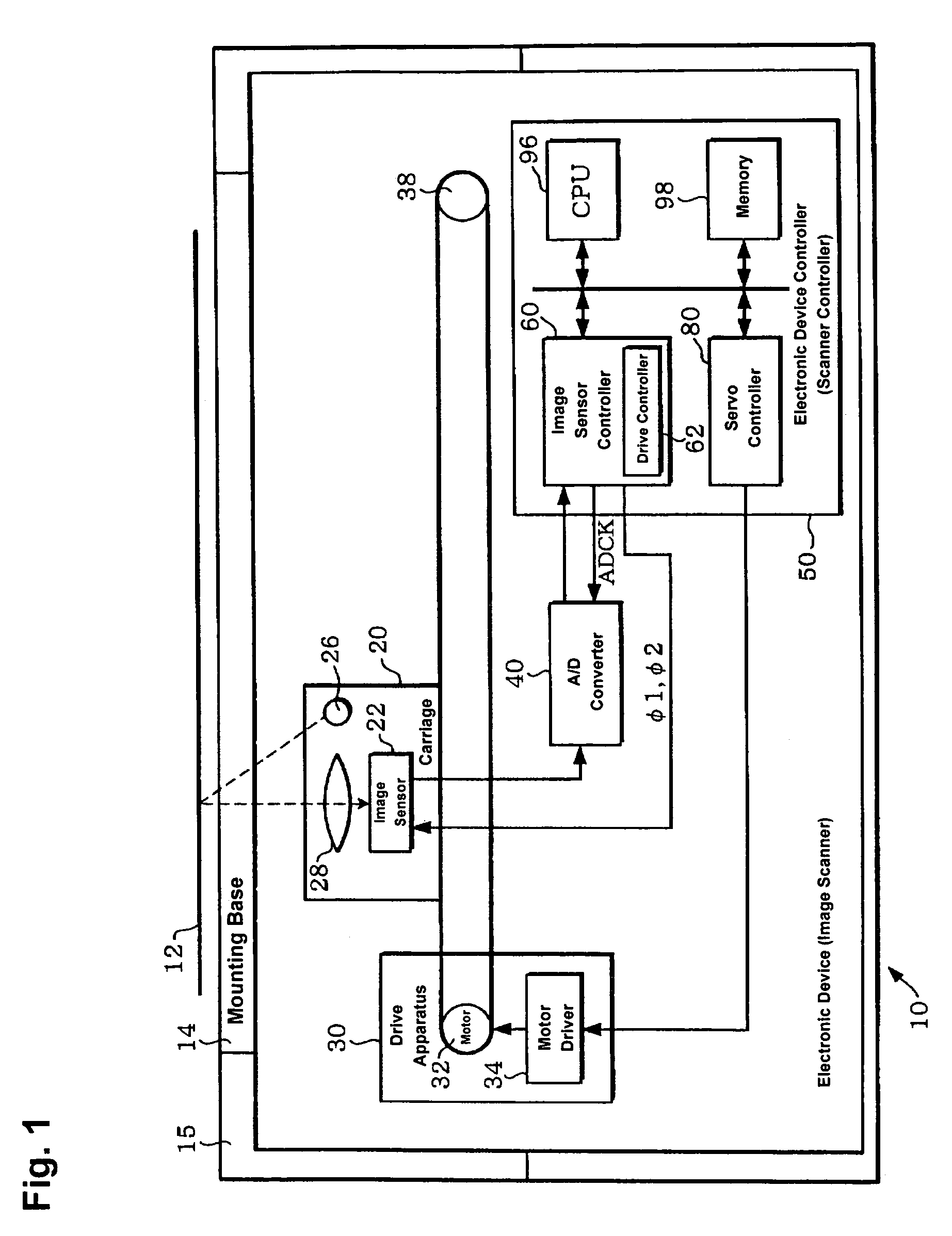
[0050]FIG. 1 shows an exemplary structure of an electronic device 10, which may be an image reading device, image scanner, or the like. As noted above, other configurations are possible, including configurations in which one or more of the illustrated components is omitted.

[0051]The electronic device 10 (e.g., a flat bed type image scanner) includes a frame 15 (e.g., a support member and housing) on which a generally rectangular mounting base 14 is carried for supporting a source object 12 (e.g., a printed document to be printed). The mounting base 14 may be formed from a light-transmitting material--glas...


PUM


Abstract

An image sensor controller and methods achieve faster image reading speeds by controlling the frequency of image sensor transfer clocks φ1, φ2 in accordance with the particular output period. Such an image sensor controller includes a drive controller that supplies to a transfer section of the image sensor transfer clocks φ1, φ2 whose clock frequency during dummy pixel output periods is faster than it is during an effective pixel output period, or whose clock frequency during non-reading pixel output periods is faster than it is during a reading pixel output period. A pattern selector selects among clock patterns in a table for setting φ1, φ2 according to the output periods of the image sensor. Even when the clock frequency of φ1, φ2 changes, a transfer clock ADCK signal can be supplied at a constant clock frequency to an A / D converter.

Description

RELATED APPLICATION DATA[0001]This application is related to two applications filed concurrently herewith: (1) entitled “Electronic Device”; and (2) entitled “Electronic Device Controller, and Method for Controlling Electronic Device”. Both of these related applications are incorporated by reference herein.BACKGROUND OF THE INVENTION[0002]1. Field of the Invention[0003]The present invention relates to image sensor controllers, electronic devices, and methods for controlling image sensors to obtain faster image reading speeds.[0004]2. Description of the Related Art[0005]An image reading device such as an image scanner, facsimile machine or copy machine uses an image sensor, i.e., Charge Coupled Device (CCD), Contact Image Sensor (CIS), or Bucket Brigade Device (BBD), to read images. A particular type of CCD (a CCD line image sensor) is usually employed in an image scanner to read images.[0006]With a line type image sensor, image information is gathered by a light receiving section of...

Claims


Application Information

Patent Timeline
Patent Type & Authority Patents(United States)
IPC IPC(8): H04N3/14G06T1/00H04N1/028H04N1/04H04N1/053H04N1/10H04N1/107H04N1/193H04N1/40
CPCH04N1/053H04N1/40056H04N1/1017H04N1/193H04N2201/04705H04N2201/04734H04N2201/04748H04N2201/04781H04N2201/03162H04N2201/04787H04N2201/02439H04N2201/04794
Inventor KIMURA, KENJISATAKE, EIJI
Owner 138 EAST LCD ADVANCEMENTS LTD
Why Eureka
Try Eureka