

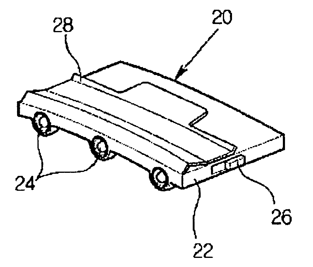
Clip type light detachably coupled with cap
a light emitter and clip technology, applied in the field of clip light emitters, can solve the problems of ensuring the user's vision field and affecting the activity of users, and achieve the effect of preventing the lamp from moving or separating, and being easy to attach or detachabl
- Summary
- Abstract
- Description
- Claims
- Application Information
AI Technical Summary
Benefits of technology
Problems solved by technology
Method used
Image

Examples
first embodiment
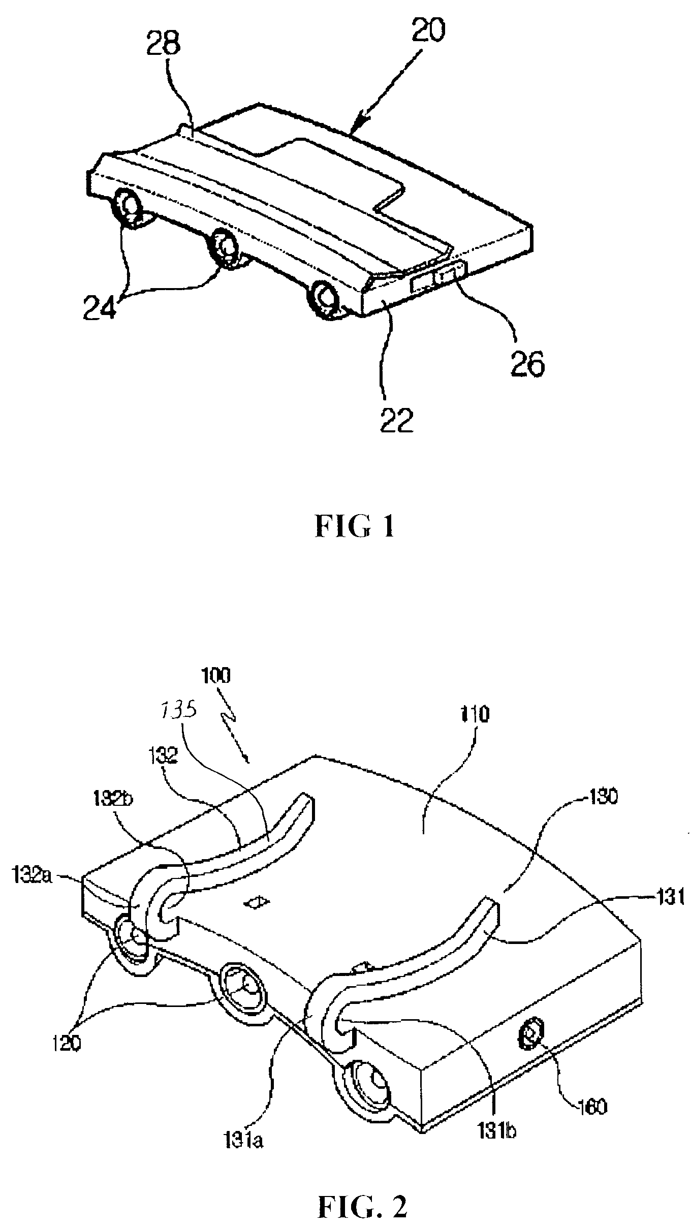
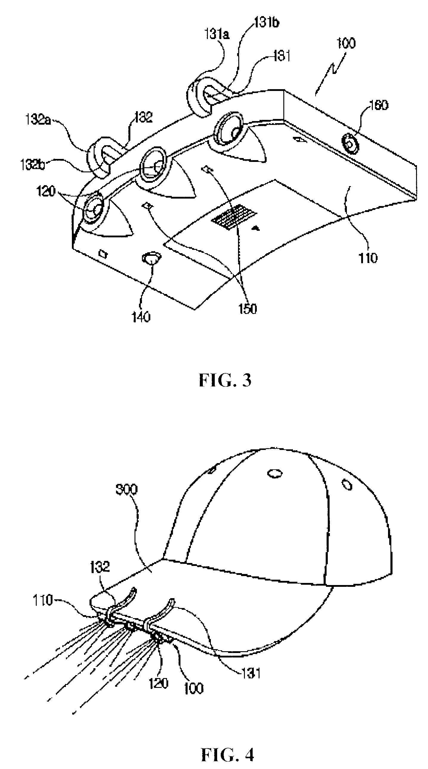
[0035]As shown in FIGS. 2, 3 and 4, the clip type light according to the present invention includes a body 110, in which a battery is accommodated. An upper portion of the body 110 closely adheres to a lower portion of a cap visor 300 having a smoothly curved surface. A plurality of electric lamps 120 are provided at the front portion of the body 110. First end portions of first and second clips 131 and 132 are fixed to the front portion of the body 110 and second end portions of the first and second clips 131 and 132 are elastically movable away from and towards the upper portion of the body 110.
[0036]The first and second clips 131 and 132 include first and second protrusions 131a and 132a, which have arc-shaped section and are integrally formed with the front portion of the body 110 while slightly protruding beyond the front portion of the body 110, and first and second clip fixing sections 135 and 136, which extend downward from the first and second protrusions 131a and 132a.
[00...
second embodiment
[0054]Hereinafter, the clip type light according to the present invention will be described with reference to FIGS. 8 to 10. The same reference numerals will be used to refer to the same elements throughout the specification.
[0055]FIG. 8 is an exploded perspective view showing the clip type light according to the second embodiment of the present invention, FIG. 9 is a perspective view showing the clip type light shown in FIG. 8 coupled with a cap visor, and FIG. 10 is a side sectional view showing the clip type light coupled with the cap visor according to the second embodiment of the present invention.
[0056]The clip type light according to the second embodiment of the present invention is substantially identical to clip type light according to the first embodiment of the present invention, except that a pair of coupling holes 170 are formed at the front portion of the body 110 and a solar cell plate 200 is coupled with the body 110 through the coupling holes 170.
[0057]As shown in F...
third embodiment
[0062]FIG. 11 is a perspective view showing a clip type light according to the present invention, and FIG. 12 is a right-side view of FIG. 11.
[0063]The clip type light according to the third embodiment of the present invention is substantially identical to the clip type light according to the first embodiment of the present invention, except for the shape of the clip.
[0064]As shown in FIGS. 11 and 12, the clip type light according to the third embodiment of the present invention includes a clip section 400 coupled to the body 110 of the clip type light. The clip section 400 is provided with a head 410 having an arc-shaped section that protrudes upward in the front direction from the front portion of the body 110. First and second clip fixing sections 411 and 413 are provided at both sides of the head 410. The first and second clip fixing sections 411 and 413 extend along the upper surface of the body 110.
[0065]A locking hole 415 is defined by means of the head 410, and the rim of th...
PUM
 Abstract
Description
Claims
Application Information