
Routing mechanism in PCI multi-host topologies using destination ID field
a routing mechanism and topology technology, applied in the field of data processing, can solve the problems of not being able to share pci adapters between clustered blades or even between multiple roots, and being costly to dedicate network adapters to each blad
- Summary
- Abstract
- Description
- Claims
- Application Information
AI Technical Summary
Benefits of technology
Problems solved by technology
Method used
Image

Examples
Embodiment Construction
[0017]The present invention applies to any general or special purpose computing system where multiple root complexes (RCs) are sharing a pool of Input / Output Adapters (IOAs) through a common I / O fabric. More specifically, the exemplary embodiments described herein detail a data routing mechanism when the I / O fabric uses PCI Express protocol.
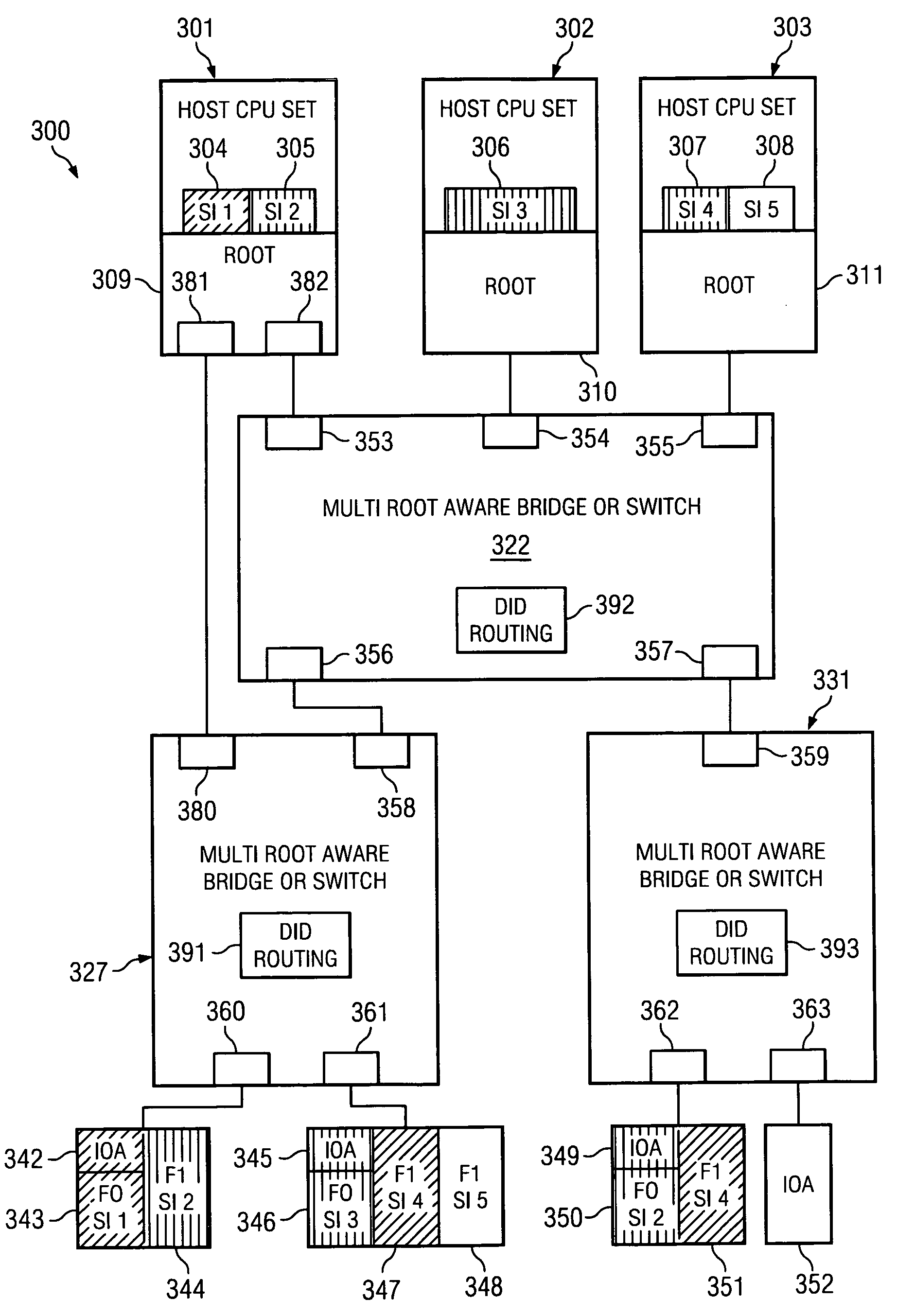
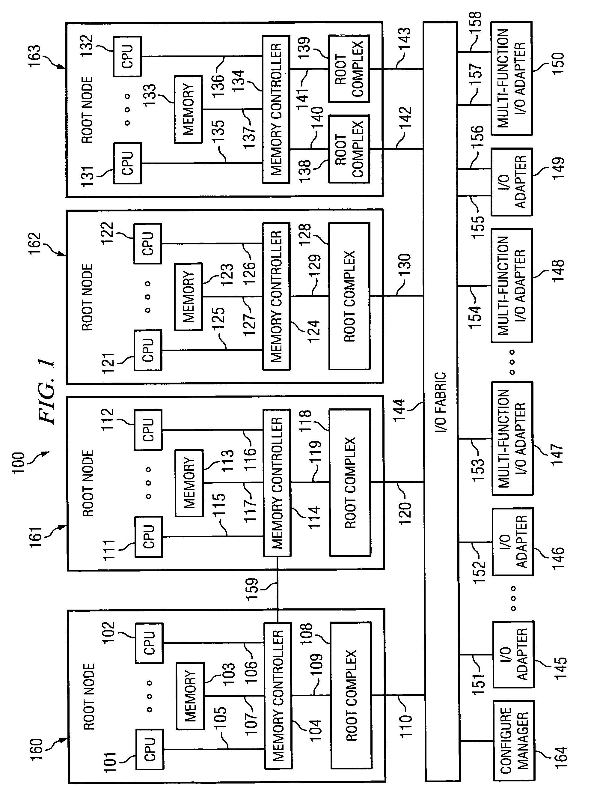
[0018]With reference now to the figures and in particular with reference to FIG. 1, a block diagram of a distributed computing system is depicted according to an exemplary embodiment of the present invention. The distributed computing system is generally designated by reference number 100 and takes the form of two or more Root Complexes (RCs), five RCs 108, 118, 128, 138 and 139 being provided in the exemplary embodiment illustrated in FIG. 1. RCs 108, 118, 128, 138 and 139 are attached to an I / O fabric 144 through I / O links 110, 120, 130, 142, and 143, respectively; and are connected to memory controllers 104, 114, 124 and 134 of root nodes (RNs...
PUM
 Abstract
Description
Claims
Application Information