Turbine assembly maintenance methods

a technology for turbine assemblies and maintenance methods, applied in the direction of sustainable transportation, mechanical equipment, machines/engines, etc., can solve the problems of limited intervention, low unit process cost, and component degradation of turbines

Active Publication Date: 2018-01-04
GENERAL ELECTRIC CO
View PDF7 Cites 13 Cited by
  • Summary
  • Abstract
  • Description
  • Claims
  • Application Information

AI Technical Summary

Benefits of technology

[0010]The methods disclosed herein are advantageous because they can be performed without dismantling or removing components that need to be maintained. These and additi

Problems solved by technology

During use, the turbine components can experience degradation.
Examples of damage that can be observed during inspection include wear (e.g., from incursion of blade tips into the shrouds, particle-induced erosion, water droplet induced erosion, wear due to sliding contact between stationary components), impact (e.g., spallation of thermal or environmental barrier coating (“TBC” or “EBC”, respectively) from turbine-section components, leading edge burring/bending of compressor blades), cracking (e.g., thermal fatigue, low-cycle fatigue or high-cycle fatigue), edge-of-contact damage between stationary parts, oxidation or hot corrosion of high-temperature metallic sections, static seal degradation, guide vane sidewall distress, and blade platform distress.
Currently, damaged components of turbine engines are primarily repaired at overhaul facilities, with only limited intervention conducted in the field.
Although the cost of the unit processes is typically lower than the replace

Method used


Image

  • Turbine assembly maintenance methods
  • Turbine assembly maintenance methods
  • Turbine assembly maintenance methods

Examples


Embodiment Construction

[0017]In the following specification and the claims which follow, reference will be made to a number of terms, which shall be defined to have the following meanings.

[0018]The singular forms “a”, “an”, and “the” include plural referents unless the context clearly dictates otherwise.

[0019]Approximating language, as used herein throughout the specification and claims, may be applied to modify any quantitative representation that could permissibly vary without resulting in a change in the basic function to which it is related. Accordingly, a value modified by a term or terms, such as “about”, is not to be limited to the precise value specified. In some instances, the approximating language may correspond to the precision of an instrument for measuring the value.

[0020]As used herein, the term “maintenance” refers to tasks associated with maintaining the condition of components of a turbine assembly. The advantages of such maintenance include the efficient operation of a turbine assembly,...


PUM


Abstract

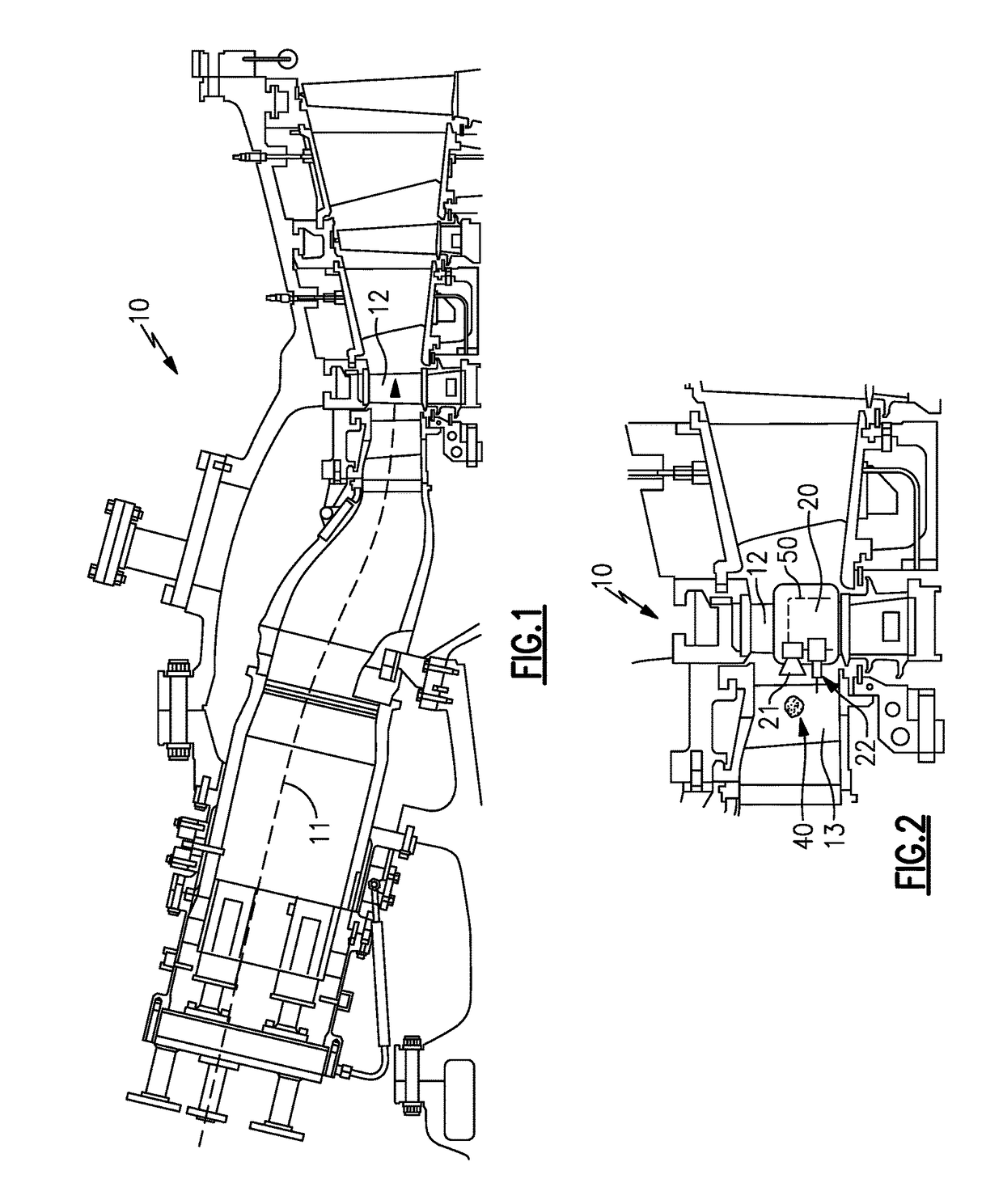
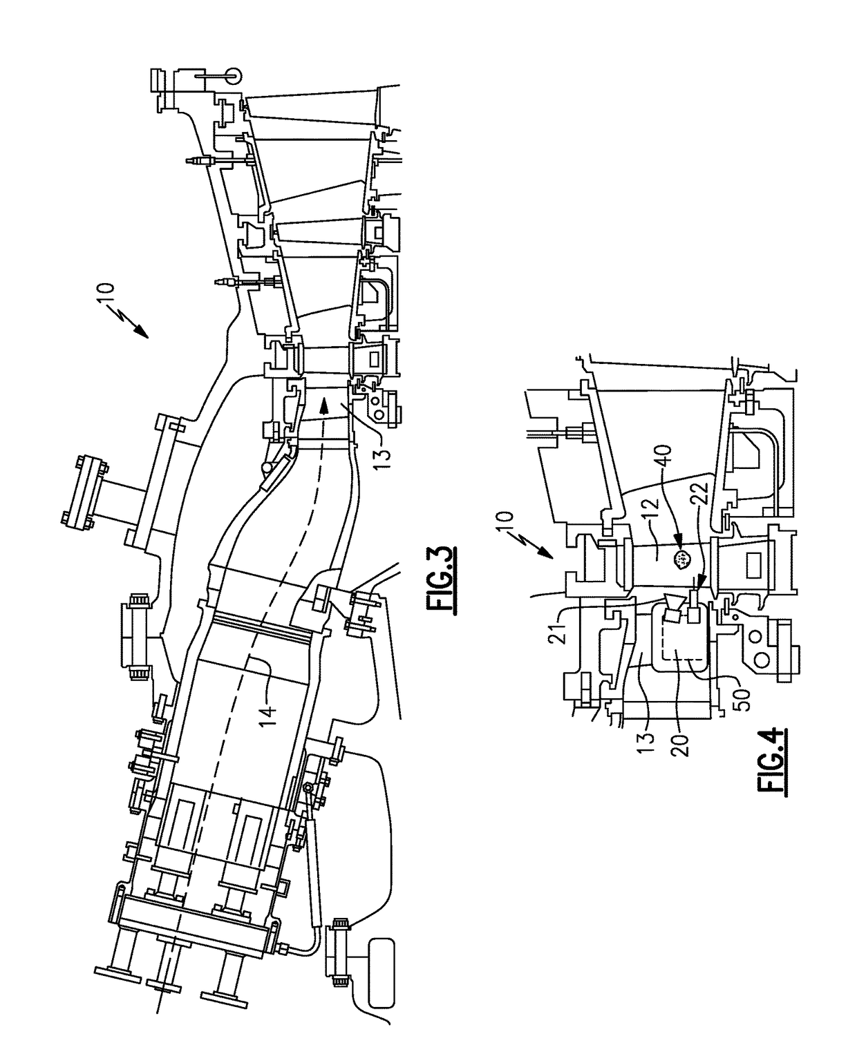
The present invention is directed to in situ methods for maintaining turbine assemblies. One such method includes: disposing a maintenance apparatus on the rotor; positioning the maintenance apparatus proximate to the damaged region by rotating the rotor; and repairing the damaged region by operating a repair tool disposed on the apparatus. Another method includes: disposing a maintenance apparatus on the stator; positioning the damaged region proximate to the maintenance apparatus by rotating the rotor; and repairing the damaged region by operating a repair tool disposed on the apparatus.

Description

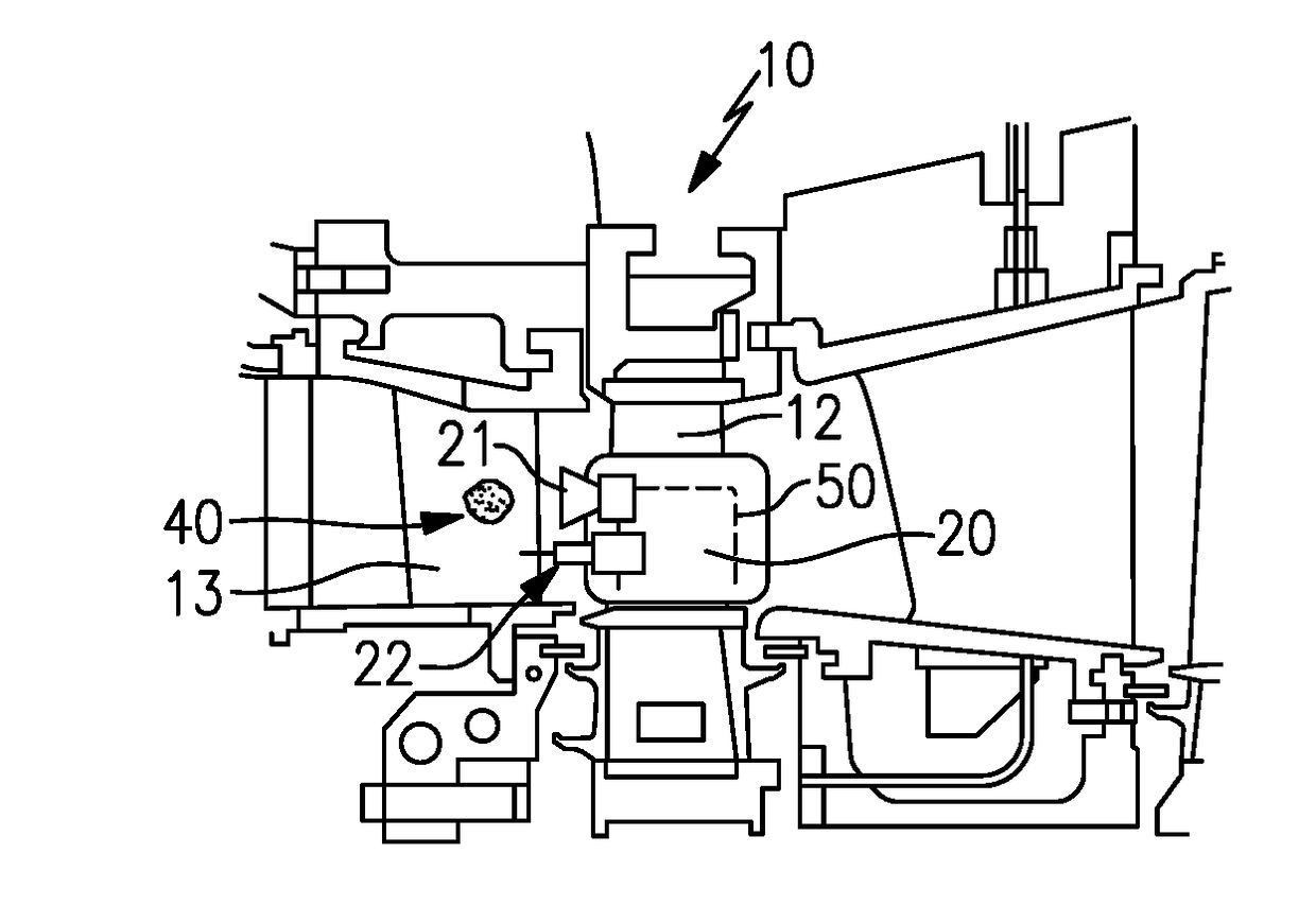
FIELD OF THE INVENTION[0001]The present invention is directed to in situ methods for maintaining turbine assemblies.BACKGROUND OF THE INVENTION[0002]Turbines for aircraft engines as well as gas and steam powered turbines for industrial applications comprise at least one rotor carrying multiple stages of airfoils (henceforth referred to as blades), which rotates with respect to the turbine case. In turn, the turbine case carries multiple stages of airfoils (henceforth referred to as guide vanes), such that the turbine consists of alternating stages of blades and guide vanes. To reduce leakage of air, steam, or combustion gas over the tips of the blades, shrouds can be disposed on the radially inner surfaces of the stator so as to form a ring seal around the blade tips. To limit air, steam, or combustion gas from entering the rotor cavities or wheel spaces, blades have platforms and guide vanes have inner sidewalls. Similarly, guide vanes have outer sidewalls to limit radially outward...

Claims


Application Information

Patent Timeline
IPC IPC(8): F01D5/00B23P6/04F01D5/02
CPCF01D5/005F01D5/02F05D2230/80F05D2220/32B23P6/045B23P6/002F01D25/285F05D2230/72H04N23/555Y02T50/60
Inventor LIPKIN, DON MARKDANKO, TODD WILLIAM
Owner GENERAL ELECTRIC CO
Why Eureka
Try Eureka