Multipoint ignition device

Active Publication Date: 2008-10-28
MIYAMA
View PDF10 Cites 6 Cited by
  • Summary
  • Abstract
  • Description
  • Claims
  • Application Information

AI Technical Summary

Benefits of technology

[0006]According to this invention, the heat values of all of the electrode pairs in a multipoint ignition device can be

Problems solved by technology

, carbon sticks to the electrode pair, and as a result, a secondary voltage leaks

Method used


Image

  • Multipoint ignition device
  • Multipoint ignition device
  • Multipoint ignition device

Examples


Embodiment Construction

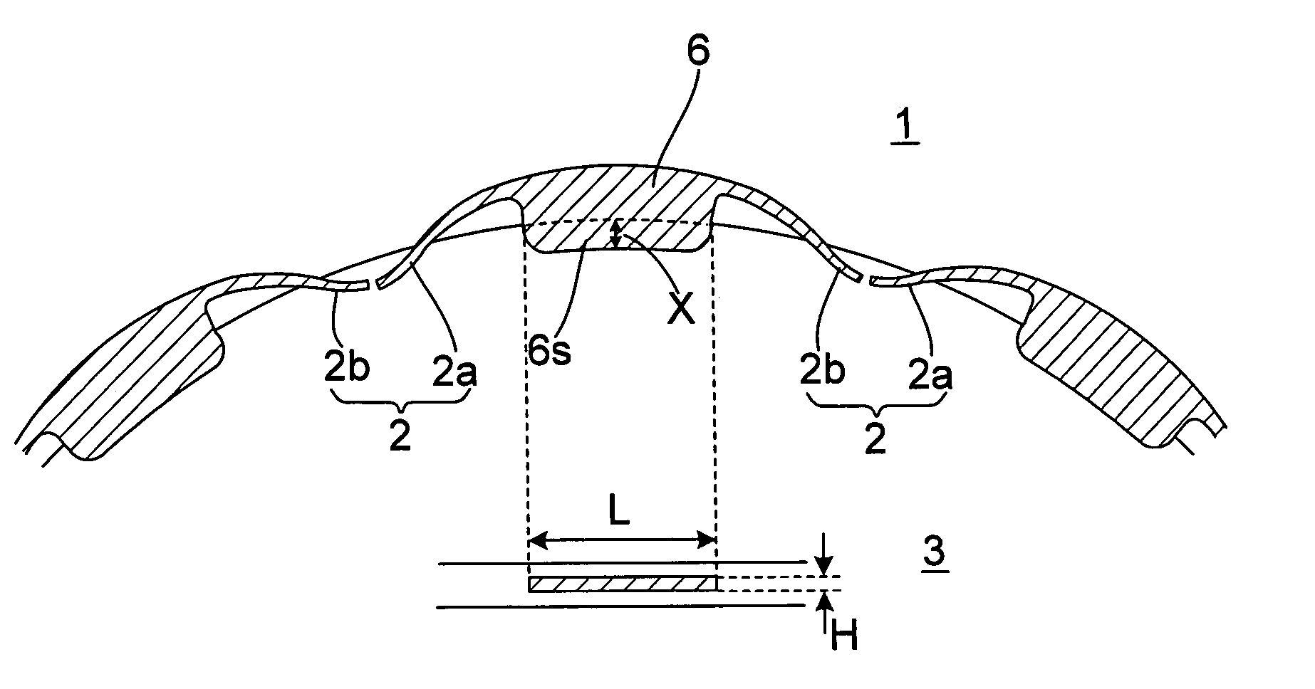
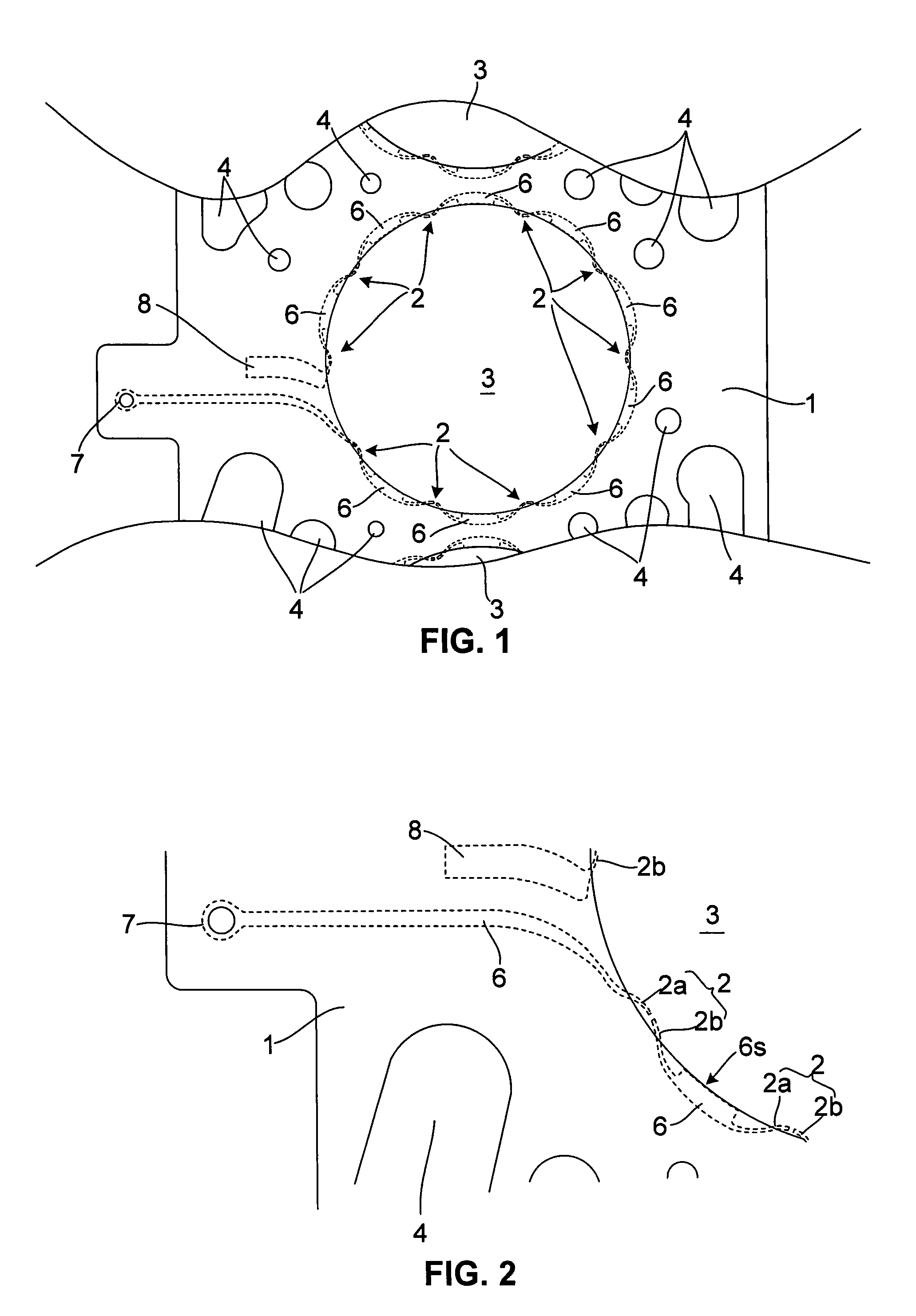
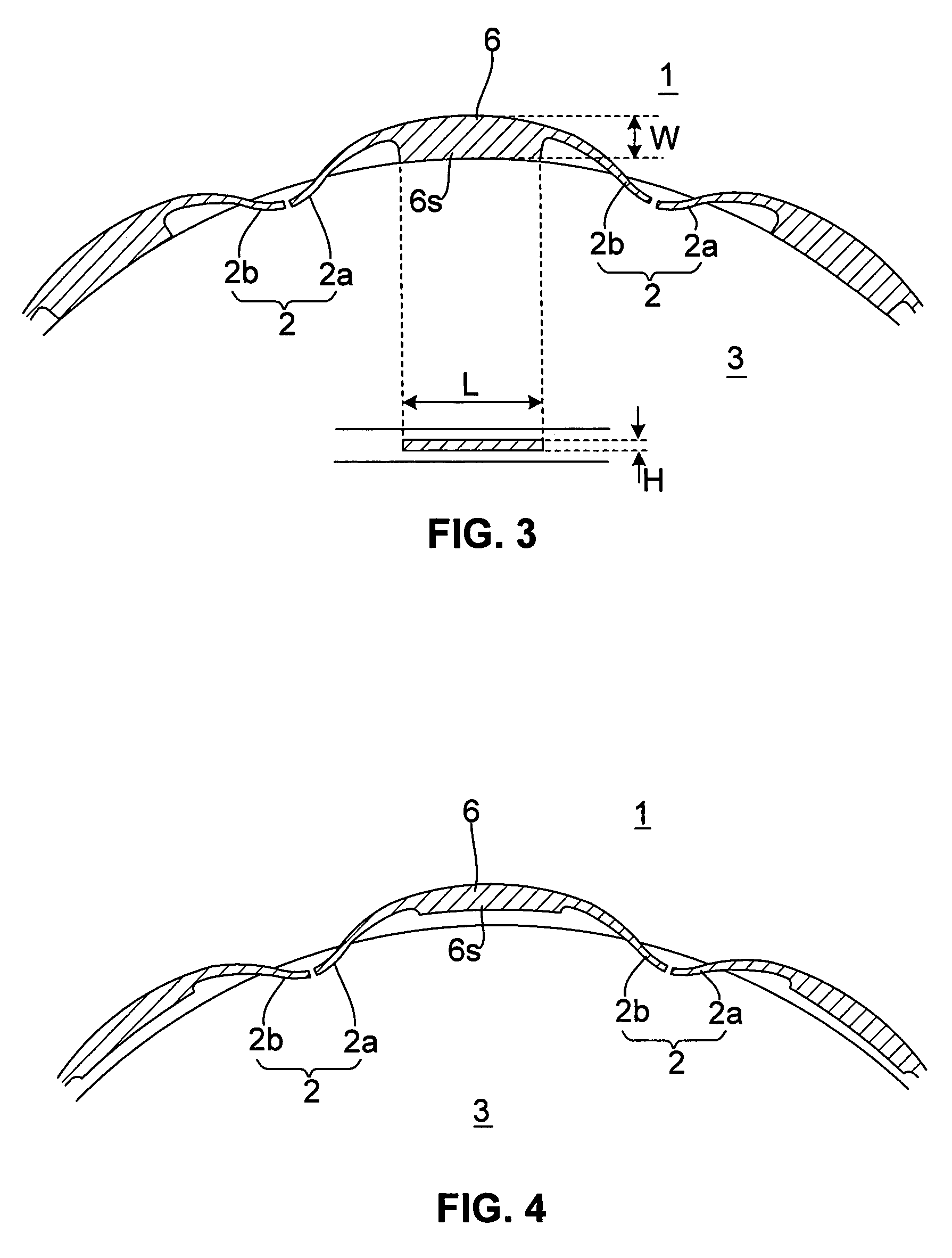
[0010]An embodiment of this invention will be described below with reference to the attached drawings. In the following description, the heat radiation property of an electrode pair is expressed as a “heat value”, similarly to a conventional spark plug. Accordingly, a good heat radiation property is referred to as a “high heat value”, and a poor heat radiation property is referred to as a “low heat value”.

[0011]FIG. 1 shows the constitution of a multipoint ignition device according to this invention, and FIG. 2 is a partially enlarged view thereof. In this embodiment, a multipoint ignition device is formed integrally with a head gasket 1 of an engine, and when the multipoint ignition device is sandwiched between a cylinder head and a cylinder block of the engine, a plurality of electrode pairs 2 are disposed around a cylinder opening portion. Each electrode pair 2 is constituted by a current-carrying electrode 2a and an earth electrode 2b, and an ignition gap is formed between the e...


PUM


Abstract

A multipoint ignition device comprises: a head gasket (1) interposed between a cylinder head and a cylinder block of an engine, having an opening (3) in a position corresponding to a cylinder opening portion; and a plurality of intermediate members (6) connected respectively to a plurality of electrode pairs (2) and held in the head gasket (1). Respective heat values of the plurality of electrode pairs (2) are set individually by varying the contact area between the plurality of intermediate members (6) and the head gasket (1) according to the respective disposal positions of the plurality of intermediate members (6).

Description

TECHNICAL FIELD OF THE INVENTION[0001]This invention relates to a multipoint ignition device used in a multipoint ignition engine having a plurality of ignition gaps in a single combustion chamber.BACKGROUND OF THE INVENTION[0002]JP2-123281A and JP1-193080A disclose a multipoint ignition engine in which a plurality of electrode pairs constituting ignition gaps are disposed around a cylinder opening portion of an engine such that an air-fuel mixture in a combustion chamber is ignited from the plurality of ignition gaps. According to this constitution, in comparison with a case in which ignition is performed using a conventional spark plug that performs ignition only from the center of the combustion chamber, combustion of the air-fuel mixture in a peripheral edge portion of the combustion chamber is promoted, enabling improvements in engine output and fuel economy.SUMMARY OF THE INVENTION[0003]When the temperature of the electrode pair is lower than a self-cleaning temperature (betwe...

Claims


Application Information

Patent Timeline
IPC IPC(8): F02P15/08
CPCF02P15/02F02P15/08H01T13/14H01T13/462
Inventor MINAMI, KATSUAKI
Owner MIYAMA
Why Eureka
Try Eureka